Dedusting system used for cupola

A technology of dust removal system and cupola, which is applied in the field of dust removal, can solve the problems of small processing capacity and inconspicuous effect, and achieve the effects of increased processing capacity, obvious processing effect and improved processing efficiency

Inactive Publication Date: 2019-12-20
湖北八环机械科技有限公司
View PDF0 Cites 0 Cited by
  • Summary
  • Abstract
  • Description
  • Claims
  • Application Information

AI Technical Summary

Problems solved by technology

[0003] The purpose of the present invention is to provide a dust removal system for cupolas in order to solve the problem that the existing cupola dust removal device has a small processing capacity and the effect is not obvious.

Method used


Image

  • Dedusting system used for cupola
  • Dedusting system used for cupola
  • Dedusting system used for cupola

Examples


Embodiment Construction

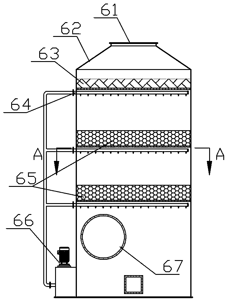
[0012] see Figure 1-3 , the present embodiment comprises the dust collecting hood 2 that is installed on the smoke outlet of the cupola 1 furnace top, the dust collecting hood 2 is connected with an induced draft fan A3 through a pipeline, and the induced draft fan A3 is connected with the air inlet of a cyclone dust collector 4, The air outlet of the cyclone dust collector 4 is connected to the air inlet of a spray tower 6 through a pipeline equipped with an induced draft fan B5, and the air outlet of the spray tower 6 is connected to the air inlet of a dehydrator 7 through a pipeline, and the dehydrator The air outlet of 7 is connected with the inlet of a chimney 9 by the pipeline that induced draft fan C8 is housed.

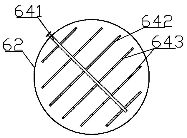
[0013] The spray tower 6 described in this embodiment includes a tank body 62, the top of the tank body 62 is provided with a spray tower gas outlet 61, the side wall of the lower end of the tank body 62 is provided with a spray tower air inlet 67, and the in...


PUM


Abstract

The invention relates to the technical field of dedusting, in particular to a dedusting system used for a cupola. The dusting system used for the cupola comprises a dust cage installed on a smoke venton the top of the cupola, and is characterized in that an induced draft fan A is connected with the dust cage through a pipeline, the induced draft fan A and an air inlet of a cyclone dust collectorare connected, an air outlet of the cyclone dust collector is connected with an air inlet of a spray tower through a pipeline provided with an induced draft fan B, an air outlet of the spray tower isconnected with an air inlet of a dehydrater through a pipeline, and an air outlet of the dehydrater is connected with an inlet of a chimney through a pipeline provided with an induced draft fan C. Bymeans of the dusting system used for the cupola, dust and sulfurous gas which are exhausted by the cupola are greatly reduced, an environmental protection effect is obvious, and the dusting system used for the cupola is suitable for modification on an existing cupola dedusting device.

Description

technical field [0001] The invention relates to the technical field of dust removal, in particular to a dust removal system for a cupola. Background technique [0002] At present, most of the smelting equipment for the production of iron castings in my country is still dominated by cupolas, but the production of cupolas produces a large amount of smoke and dust, which is particularly serious for environmental pollution. The general dust removal method is to install a dust removal device on the top of the chimney of the cupola. To reduce the emission of smoke and dust, but this method has a small amount of treatment, and the discharged gas contains sulfur and other harmful substances, and the treatment effect is not obvious. Contents of the invention [0003] The purpose of the present invention is to provide a dust removal system for cupolas in order to solve the problems of small processing capacity and inconspicuous effect of existing cupola dust removal devices. [0004...

Claims


Application Information

Patent Timeline
Patent Type & Authority Applications(China)
IPC IPC(8): B01D50/00B01D53/78B01D53/48B01D53/04B01D53/26
CPCB01D53/78B01D53/48B01D53/04B01D53/26B01D2258/0283B01D50/40
Inventor 陈国清
Owner 湖北八环机械科技有限公司
Why Eureka
Try Eureka