Access floor panel having intermingled directional and non-directional air passageways

a technology of air passageways and access floor panels, which is applied in the direction of electrical apparatus construction details, lighting and heating apparatus, heating types, etc., can solve the problems of generating a relatively high amount of heat, unable to be used in every access floor system application, and the associated peripheral equipment and cables

Active Publication Date: 2013-08-20
TATE ACCESS FLOORS INC
View PDF23 Cites 11 Cited by
  • Summary
  • Abstract
  • Description
  • Claims
  • Application Information

AI Technical Summary

Benefits of technology

[0045]One advantage of the air directional panels of this invention is that they can be designed to direct air evenly throughout the height of adjacent structure and / or equipment, such as an IT rack. That directional cooling air flow results in more consistent cooling throughout the height of the adjacent structure and / or equipment and more economic cooling of that structure and / or equipment because less air bypasses the racks.

Problems solved by technology

Those racks, and the associated peripheral equipment and cables, generate a relatively high amount of heat.
However, grated access floor panels cannot be used in every access floor system application.

Method used


Image

  • Access floor panel having intermingled directional and non-directional air passageways
  • Access floor panel having intermingled directional and non-directional air passageways
  • Access floor panel having intermingled directional and non-directional air passageways

Examples


Embodiment Construction

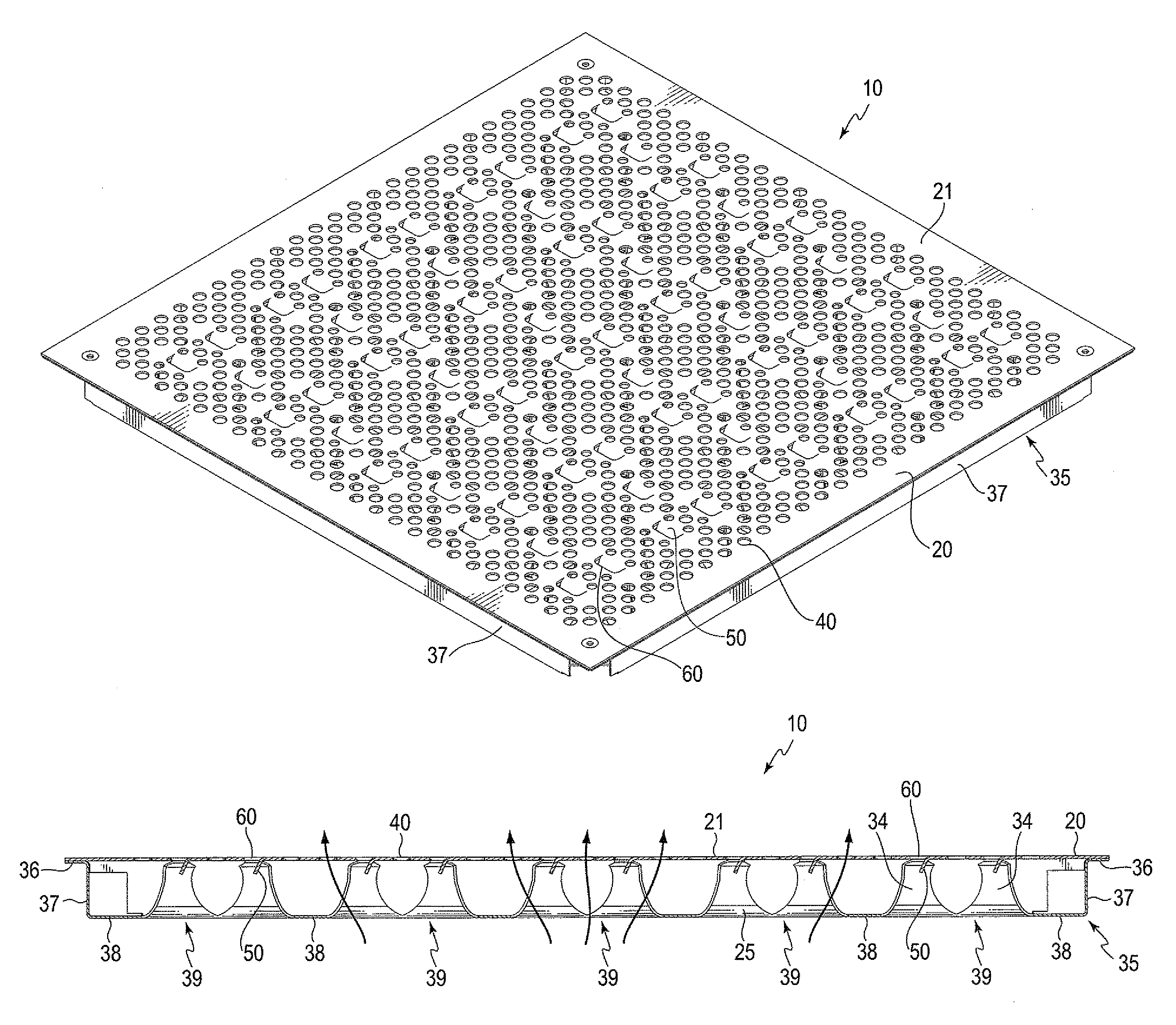
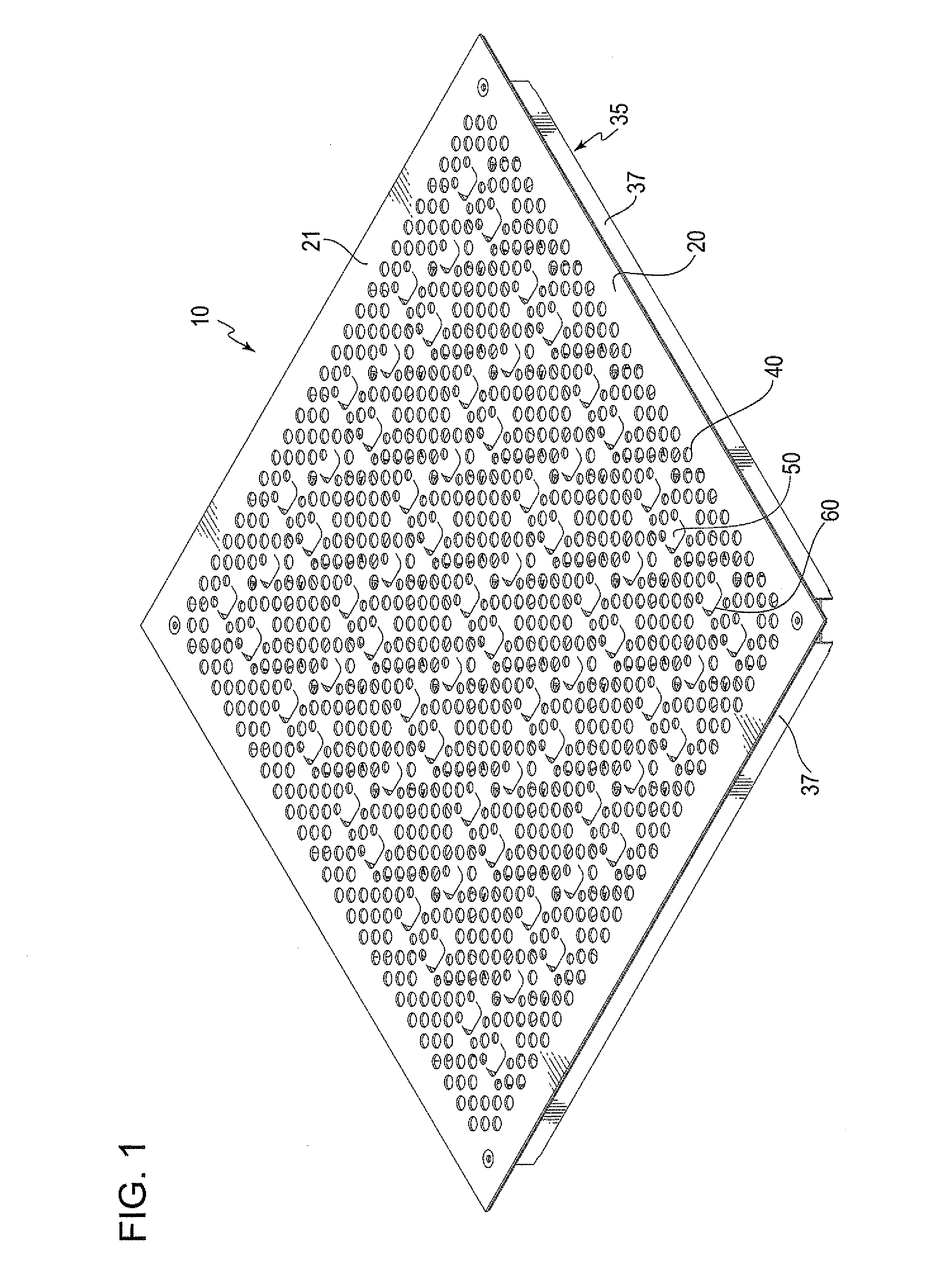
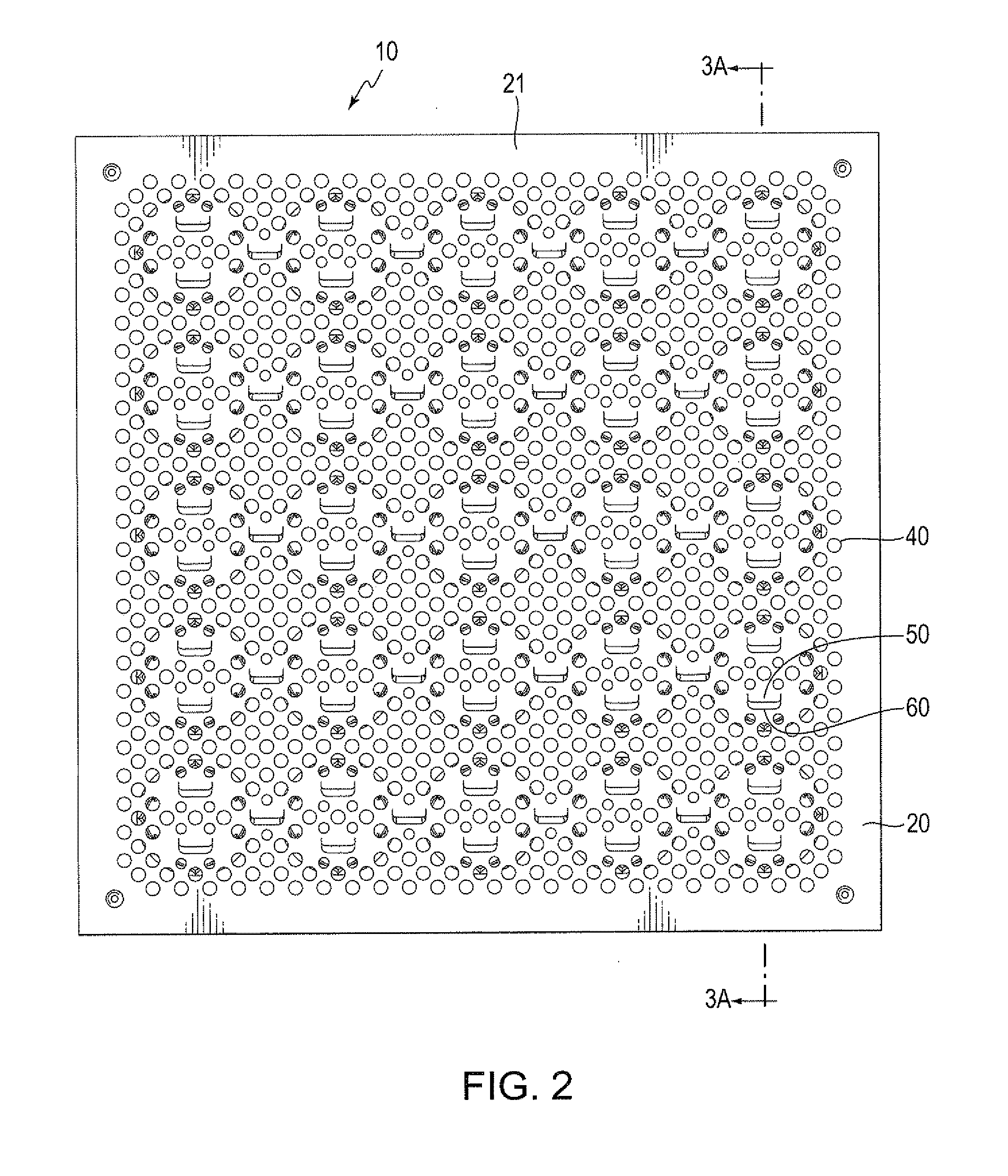
[0023]Air directional access floor panel 10 is illustrated in FIGS. 1-4B. Panel 10 includes supporting substructure 35 and top plate 20. Top plate 20 is attached on top of supporting substructure 35. In other embodiments, top plate 20 and supporting substructure 35 can be a unitary structure.

[0024]Air directional access floor panel 10 can be made of any material or combination of materials that is capable of providing the structural rigidity required for a given application. Preferably, panel 10 is made of a metal or a combination of materials that includes metal.

[0025]In this embodiment, supporting substructure 35 is a unitary sheet of metal that has been shaped and formed such that it has outer lip 36, side wall 37, bottom wall 38, wells 39 and fingers 34.

[0026]Outer lip 36 is horizontal and forms the periphery of supporting substructure 35. The periphery of top plate 20 is attached to outer lip 36.

[0027]Sidewall 37 extends downwardly from the inside edge of outer lip 36 and forms...


PUM


Abstract

An access floor panel is disclosed that has a top plate with a plurality of non-directional air passageways intermingled with a plurality of directional air passageways. The directional air passageways are configured to direct airflow through them at an angle to the upper surface of the top plate of other than 90°. The directional air passageways include an opening in the top plate and a tab adjacent to each opening that is at an angle with respect to top surface of the top plate of other than 90°. Due to the intermingling of the non-directional air passageways and the directional air passageways, the composite air flow direction through the non-directional air passageways and the directional air passageways is at an angle with the top plate of other than 90°.

Description

BACKGROUND[0001]1. Field of the Invention[0002]This invention relates to access floor panels. In particular, this invention relates to access floor panels having spaced openings or passageways for air to pass through the panels.[0003]2. Background of the Invention[0004]A typical data center includes multiple IT racks. Those racks, and the associated peripheral equipment and cables, generate a relatively high amount of heat. Because of that heat, providing adequate cooling to the IT racks in a data center is of paramount importance. Moreover, it is desirable that the IT racks be cooled as efficiently as possible, as the energy costs to cool IT racks may approach a large percentage of the energy costs to operate the data center.[0005]Data centers typically have a raised floor system, often called an access floor system. An access floor system is usually comprised of a continuous array of access floor panels, arranged edge-to-edge, and supported above the sub-floor by support structure...

Claims


Application Information

Patent Timeline
Patent Type & Authority Patents(United States)
IPC IPC(8): E04B1/70
CPCE04F15/02405H05K7/20745F24F13/068E04F15/02417
Inventor CURTIN, DANIEL J.REYNOLDS, WILLIAM W.KENNEDY, DANIEL B.
Owner TATE ACCESS FLOORS INC
Why Eureka
Try Eureka