
Remote ballast housing with airflow channel

a ballast housing and remote technology, applied in the direction of lighting and heating apparatus, traffic signals, roads, etc., can solve the problems of limited ability to tolerate high temperatures, overheating is a common problem, and insufficient heat dissipation of power-related components such as ballasts, lamps and lamp sockets, etc., and achieve the effect of free cooling

Active Publication Date: 2013-08-20
IDEAL IND LIGHTING LLC
View PDF30 Cites 21 Cited by
  • Summary
  • Abstract
  • Description
  • Claims
  • Application Information

AI Technical Summary

Benefits of technology

The invention provides a high-intensity discharge lighting fixture with improved heat dissipation. The fixture has a ballast housing with an airflow channel that allows air to flow freely between the ballast housing and the optics housing, which helps to transfer heat out of the fixture and into the atmosphere. This results in improved cooling of the fixture and better performance.

Problems solved by technology

Because outdoor commercial fixtures are often large, such fixtures of the prior art suffer from several disadvantages.
For example, overheating is a common problem in such lighting fixtures.
Among the overheating problems with certain devices of the prior art is a problem of inadequate heat dissipation away from power-related components such as ballasts, lamps and lamp sockets.
Certain components, particularly capacitors, ballasts and ignitors, etc., are limited in their ability to tolerate high temperatures.
Overheating can damage power-related components which compromises the longevity of the lighting fixture and its components.
Each of these attempts to address the concern of overheating have disadvantages and, in some cases, have exacerbated the problem.
Additionally, lighting fixtures of the prior art show that certain attempts to contain any overheating have made achieving a pleasing appearance difficult at best.
While commercial outdoor lighting fixtures are critical for safety of an area, the appearance of such fixtures has long been sacrificed in the interests of pure utility.
In addition to overheating concerns, certain fixtures of the prior art sacrifice space within the optics housing by incorporating the power-related components within the same housing.
This reduces the space available for the reflector which in turn reduces the performance of the fixture.

Method used


Image

  • Remote ballast housing with airflow channel
  • Remote ballast housing with airflow channel
  • Remote ballast housing with airflow channel

Examples


Embodiment Construction

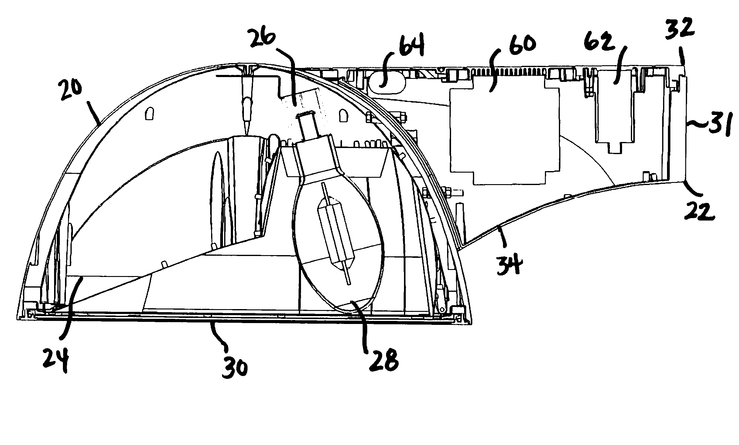
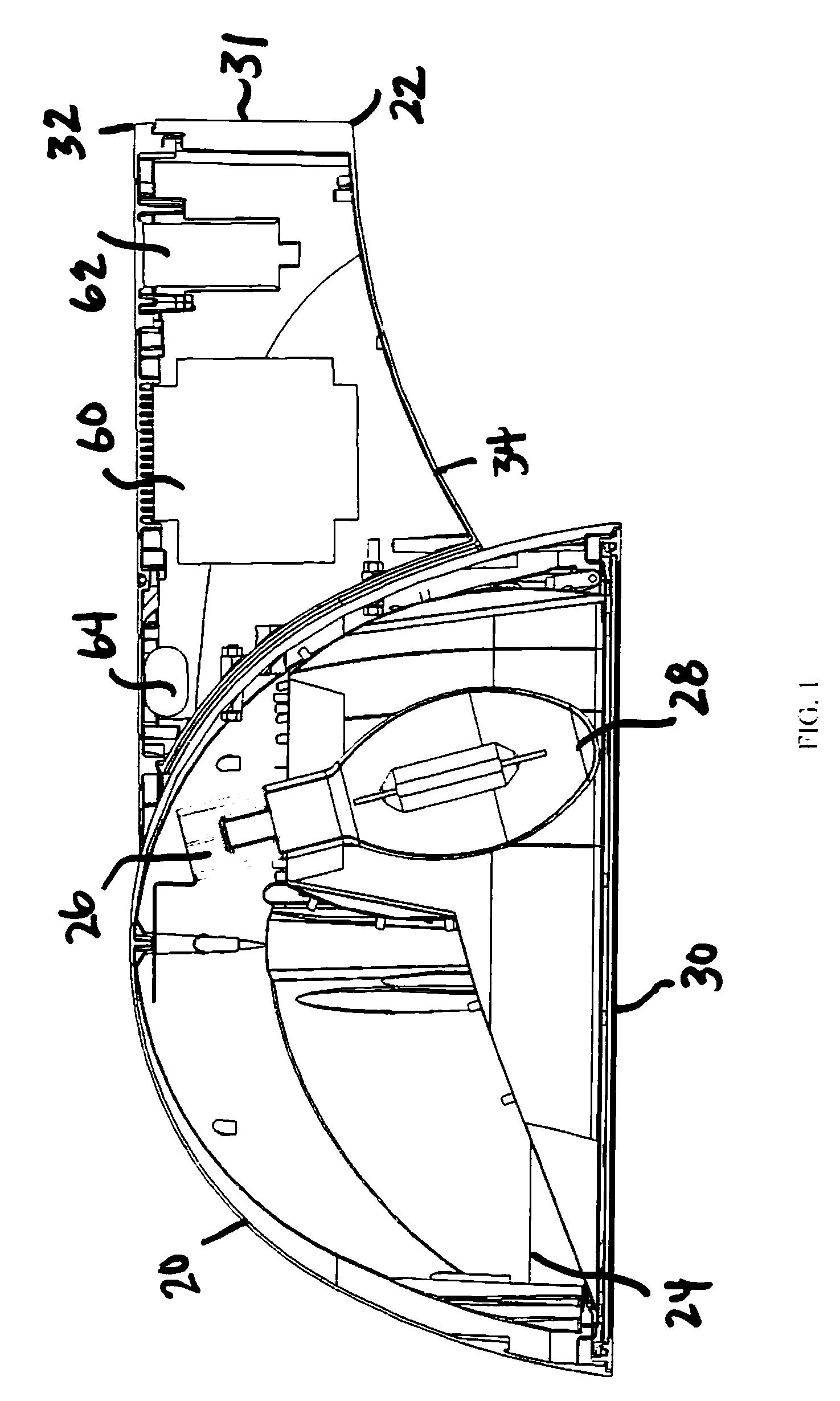
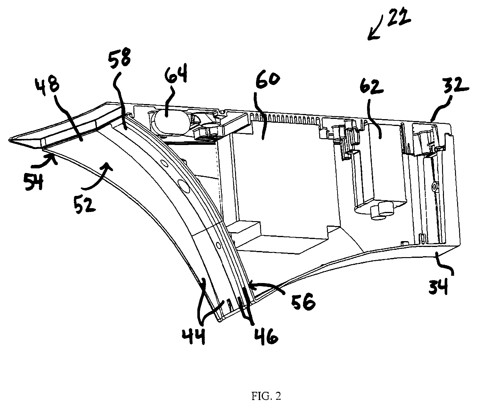
[0033]FIG. 1 illustrates a preferred embodiment of the high-intensity discharge lighting fixture, wherein the lighting fixture 10 is illustrated in cross-section. As shown in FIGS. 1 and 10, lighting fixture 10 comprises an optics housing 20 and a separate ballast housing 22. Optics housing 20 includes the optical components, namely, at least a reflector 24, a lamp holder 26, a lamp 28 and a lens 30. Though lighting fixture 10 preferably includes a high-intensity discharge lamp, other types of lamps could be used. Ballast housing 22, as illustrated, is a side-arm housing having an arcuate shape. However, it should be recognized that ballast housing 22 may have other shapes, for example, a rectangular-shaped arm. Ballast housing 22 may be of any shape suitable for separately housing the power-related components and for supporting optics housing 20. Ballast housing 20 includes a distal endwall 31 that is adapted for pole mounting. Both optics housing 20 and ballast housing 22 are pref...


PUM


Abstract

A high-intensity discharge lighting fixture of the type having an optics housing and optics components mounted therein, the fixture comprises a ballast housing having a first member and a second member including at least one airflow channel integrally formed therein, the airflow channel is positioned immediately adjacent the optics housing and is adapted to facilitate free airflow between the ballast housing and the optics housing whereby heat is dissipated from the lighting fixture to the atmosphere.

Description

FIELD OF THE INVENTION[0001]This field relates generally to commercial lighting fixtures, such as outdoor commercial lighting fixtures, and more specifically to such outdoor commercial lighting fixtures having high-intensity discharge lamps.BACKGROUND OF THE INVENTION[0002]Commercial outdoor lighting fixtures are important not only for the safety and security they provide, but also for their aesthetic contribution to the environment. Such fixtures should blend harmoniously with the landscape while maintaining their utilitarian characteristics. Outdoor lighting fixtures are commonly used in public ways, recreational areas, parking lots, walkways and the like. High-intensity discharge lighting is most commonly used in outdoor applications where a lot of light is required. Among advances in outdoor commercial lighting fixtures are the fixtures disclosed in U.S. Pat. No. 7,097,330 (Outdoor Lighting Fixture); U.S. Pat. No. 6,481,867 (Modular Luminaire Assembly); U.S. Pat. No. 5,918,970 (...

Claims


Application Information

Patent Timeline
Patent Type & Authority Patents(United States)
IPC IPC(8): B60Q1/06E01F9/00F21V7/20F21V29/00F21V29/505
CPCF21V23/026F21V29/83F21V29/004F21W2131/10
Inventor HAUGAARD, ERIC J.SCHULTZ, RUSSELL S.
Owner IDEAL IND LIGHTING LLC
Learn More