Hybrid digital-to-synchro converter unit

Inactive Publication Date: 2013-08-20
THE UNITED STATES OF AMERICA AS REPRESENTED BY THE SECRETARY OF THE NAVY
View PDF29 Cites 0 Cited by
  • Summary
  • Abstract
  • Description
  • Claims
  • Application Information

AI Technical Summary

Benefits of technology

[0017]Inventive products can surpass existing commercial products in terms of superior performance, reasonable price, acute precision, and on-demand availability. A typical embodiment of an inventive DSC: has about the same length and width as have currently available devices; uses timer interrupts to perform routine tasks, floating-point calculations, and input/output processes; supports 60 Hz and 400 Hz synchro generations up to 90 VAC; is capable of receiving input over an SPI bus as well as 10-16 bits parallel input; offers 10-16 bits (e.g., 10/12/14/16 bits) input values selection, and thus is more versatile than devices offering 14 bits input value; can be manufactured using off-the-shelf parts and components, thus affording benefits in cost-effectiveness and design robustness; offers 10 VA load capability (versus currently available 4 VA capability) without compromising price, accuracy, and performance; can provide automatic overload and overheat shutdown funct

Problems solved by technology

Frequently, commercially available synchros are beset with monopolistic high costs, long procurement lead times, and inadequate accuracy.
Among the technical problems that have been encountered through use of currently available digital-to-synchro converter units (DSCU) are the following: inability to drive a large load (resistive, inductive, or capacitive), e.g., of higher th

Method used


Image

  • Hybrid digital-to-synchro converter unit
  • Hybrid digital-to-synchro converter unit
  • Hybrid digital-to-synchro converter unit

Examples


Example

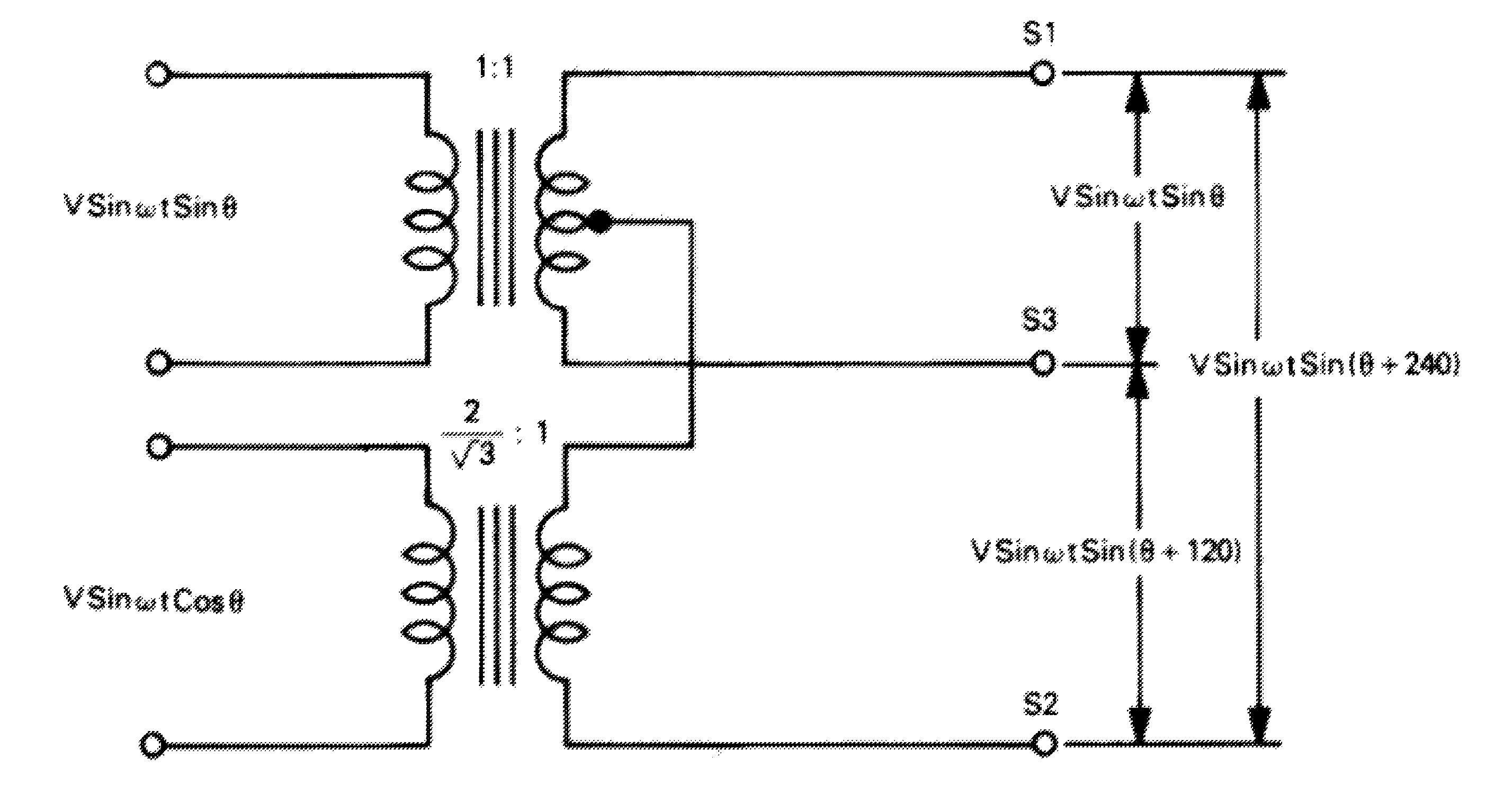
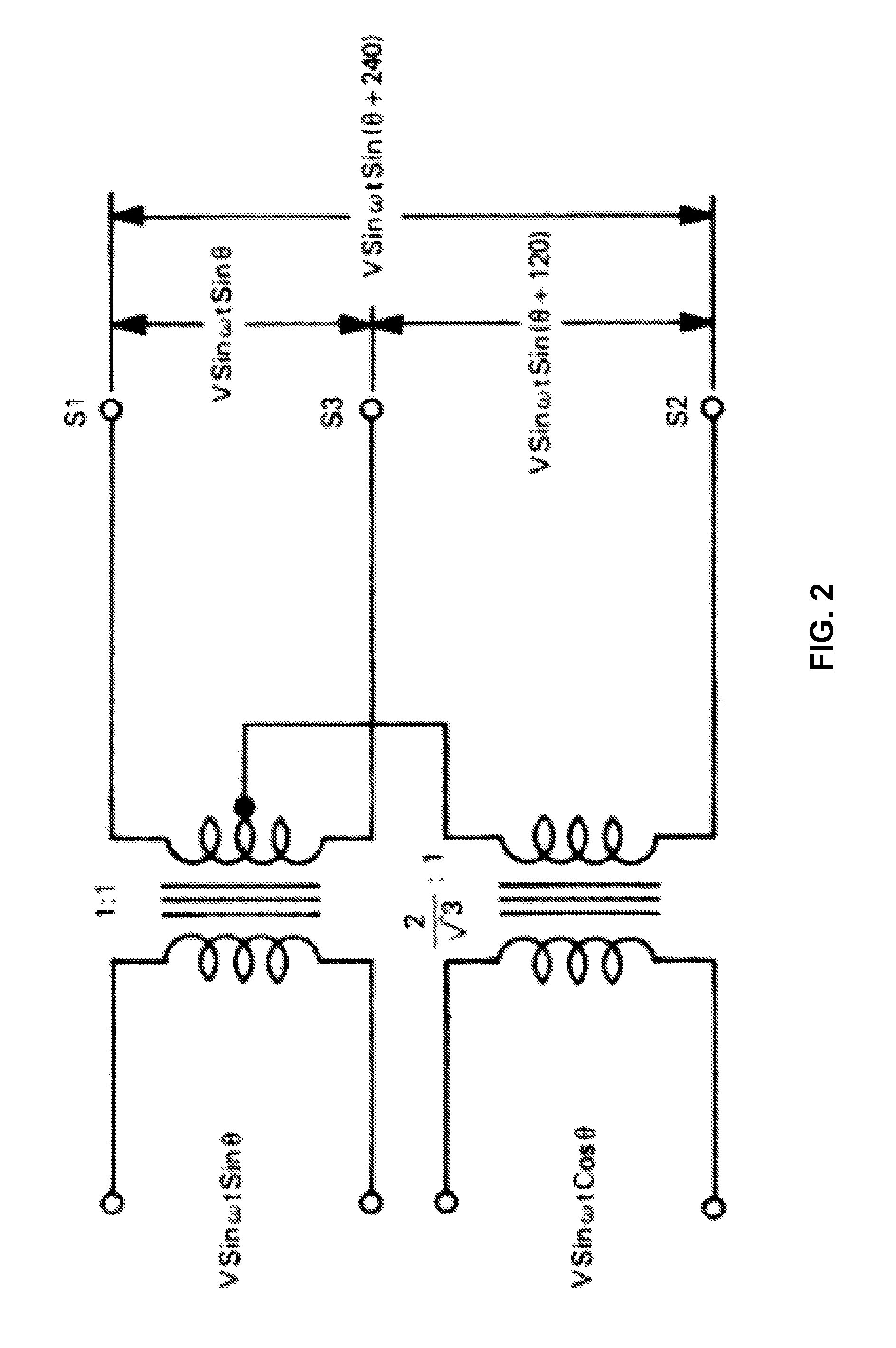
[0030]An important distinction between the inventive digital-to-synchro conversion device and traditional digital-to-synchro conversion devices is that the inventive device does not use a “Scott-T” transformer, a type of circuit such as illustrated in FIGS. 1 and 2. FIG. 2 is a simplified digital-to-synchro circuit diagram taken from the aforementioned DDC Synchro / Resolver Conversion Handbook, 4th Edition, page 47.

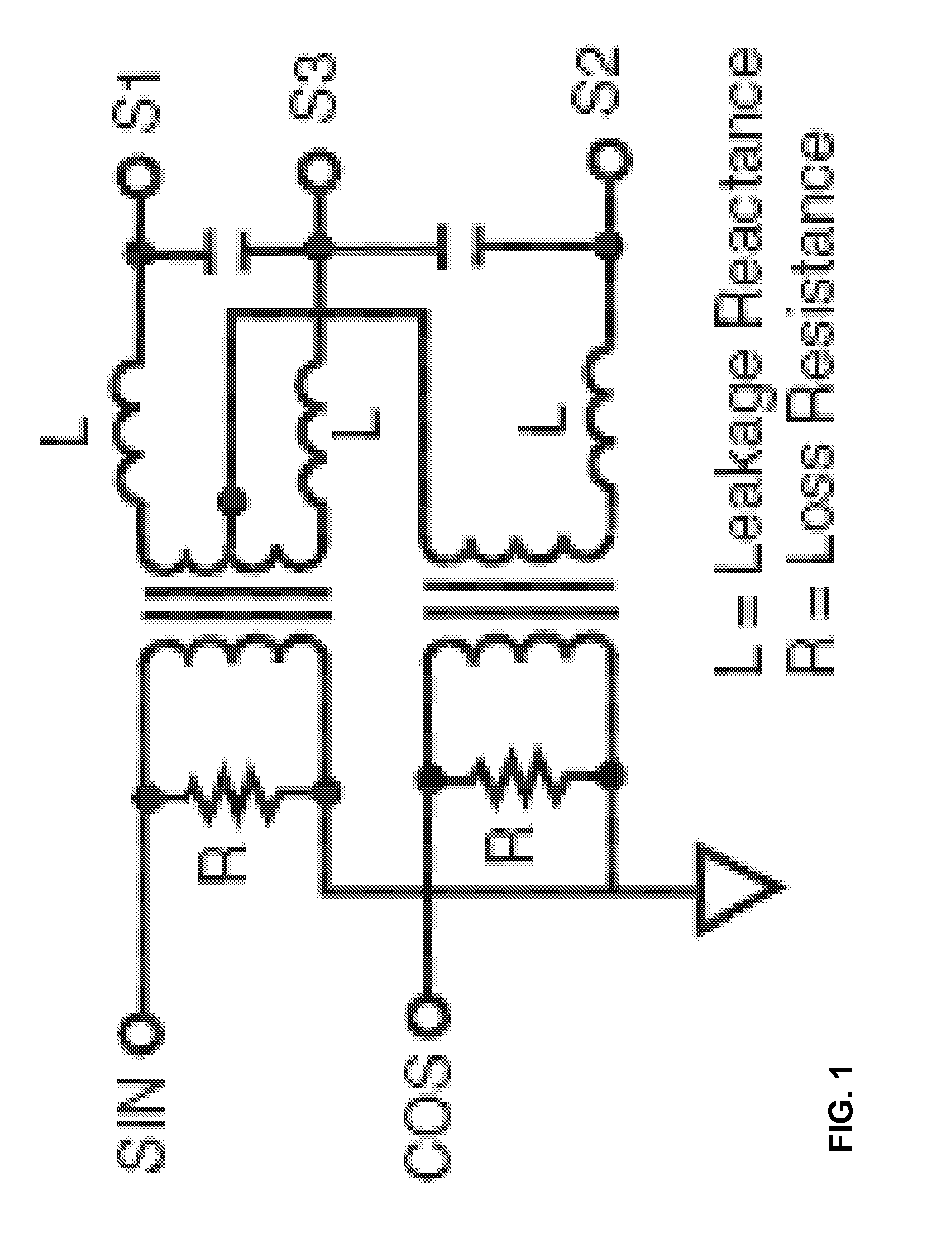
[0031]Commercially available digital-to-synchro conversion units use a Scott-T transformer exclusively. As shown in FIGS. 1 and 2, according to traditional principles of a Scott-T transformer, its secondary coil windings convert [V Sin({acute over (ω)}t) Sin(Φ)] and [V Sin({acute over (ω)}t) Cos(Φ)], which are input to the primary coil. The Scott-T transformer outputs [V Sin({acute over (ω)}t) Sin(Φ)], [V Sin({acute over (ω)}t) Sin(Φ+120)], and [V Sin({acute over (ω)}t) Sin(Φ+240)] as S1, S2, and S3 synchro signals.

[0032]FIGS. 1 and 2 illustrate the mathematics of the sign...


PUM


Abstract

A digital-to-synchro converter (“DSC”) is a device that converts digital signals to analog signals suitable for use by a synchro device. A conventional DSC implements complex circuitry to take digital input and generate [V Sin({acute over (ω)}t) Sin(Φ)] and [V Sin({acute over (ω)}t) Cos(Φ)] analog signals, and a Scott-T transformer to transform these analog signals into [V Sin({acute over (ω)}t) Sin(Φ)], [V Sin({acute over (ω)}t) Sin(Φ+120)], and [V Sin({acute over (ω)}t) Sin(Φ+240)] analog signals. An inventive DSC, as typically embodied, implements a microcontroller to take digital input and generate [V Sin({acute over (ω)}t) Sin(Φ)] and [V Sin({acute over (ω)}t) Sin(Φ+120)] digital signals, a digital-to-analog converter to convert these digital signals to [V Sin({acute over (ω)}t) Sin(Φ)] and [V Sin({acute over (ω)}t) Sin(Φ+120)] analog signals, and a regular transformer (i.e., non-Scott-T transformer) to transform these analog signals (typically, in amplified voltage form) into [V Sin({acute over (ω)}t) Sin(Φ)], [V Sin({acute over (ω)}t) Sin(Φ+120)], and [V Sin({acute over (ω)}t) Sin(Φ+240)] analog signals. Inventive practice is accurate, versatile, and economical.

Description

BACKGROUND OF THE INVENTION[0001]The present invention relates to synchros, more particularly to methods and devices for converting digital signals to a synchro's analog signals.[0002]Synchros are analog electronic devices that have been used for many years, in both military and commercial contexts, for providing angular, positional, and other information pertaining to navigation, communication, detection, weaponry, etc. The noun “synchro” derives from the adjective “synchronous.” Generally speaking, synchros look like electric motors (insofar as including a rotor, a stator, and a shaft) and operate like rotary electrical transformers. A synchro is a type of electrical transformer that measures and sets the angle of a rotating device.[0003]Digital-to-synchro conversion is conversion of digital signals to synchro (analog) signals. Such conversion is necessary in order for synchros to make use of digital signals transmitted by any of various forms of digital (e.g., computer) technolog...

Claims


Application Information

Patent Timeline
IPC IPC(8): H03M1/22
CPCH03M1/665
Inventor PATEL, BHAVESH V.
Owner THE UNITED STATES OF AMERICA AS REPRESENTED BY THE SECRETARY OF THE NAVY
Why Eureka
Try Eureka