Mechanical power transmission system and method

a technology of power transmission system and mechanical transmission system, which is applied in the direction of mechanical actuated clutches, interengaging clutches, gearing, etc., can solve the problems of not disclosing a new mechanical power transmission system, and achieve the effect of reducing weight, effective speed change, and increasing fuel efficiency

Inactive Publication Date: 2013-08-27
BROOKINS ERNIE
View PDF8 Cites 56 Cited by
  • Summary
  • Abstract
  • Description
  • Claims
  • Application Information

AI Technical Summary

Benefits of technology

[0010]Still another object of the present invention is to provide a new mechanical power transmission system that uses external pressure to effectively change speeds.
[0011]Still yet another object o...

Problems solved by technology

While these devices fulfill their respective, particular objectives and requirement...

Method used


Image

  • Mechanical power transmission system and method
  • Mechanical power transmission system and method
  • Mechanical power transmission system and method

Examples


Embodiment Construction

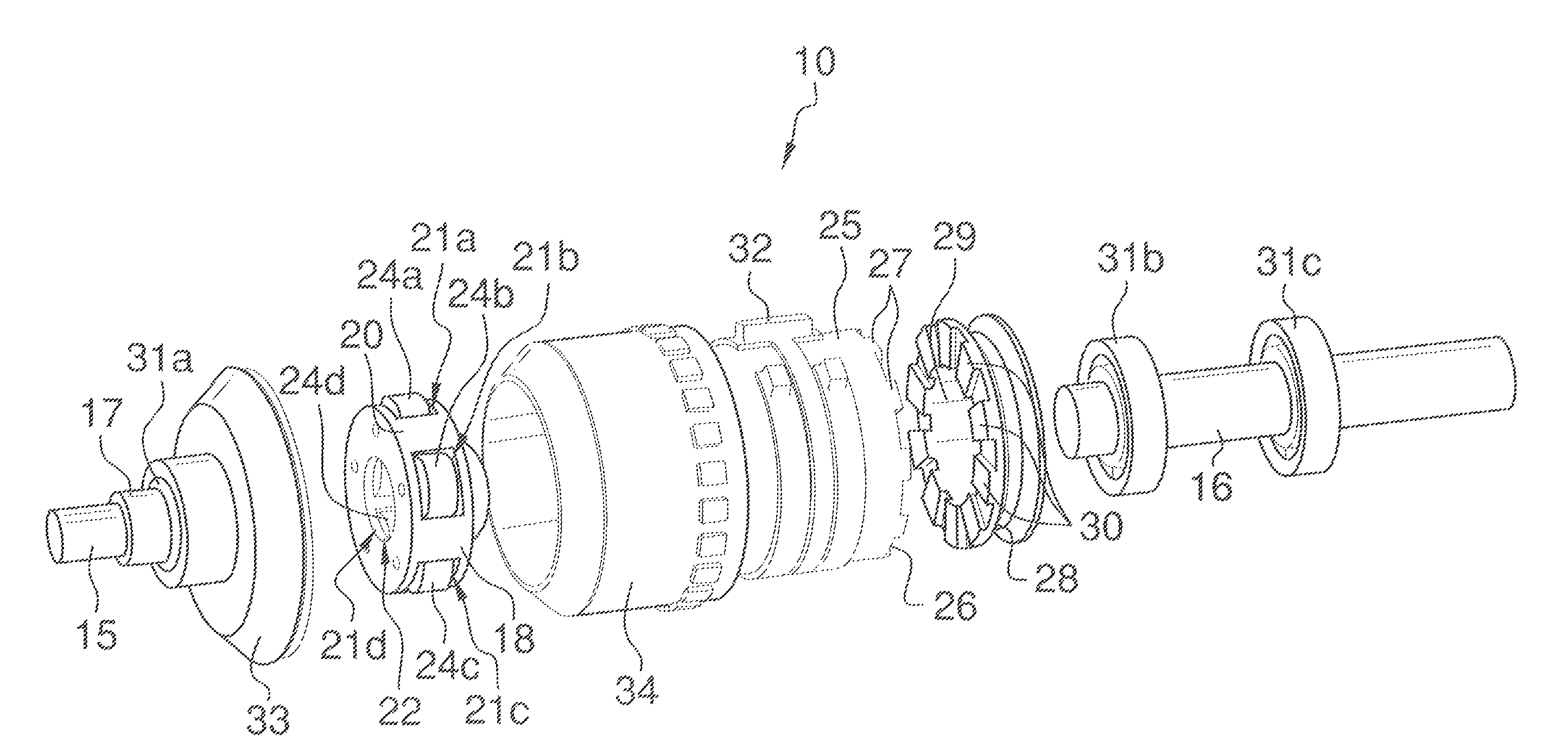
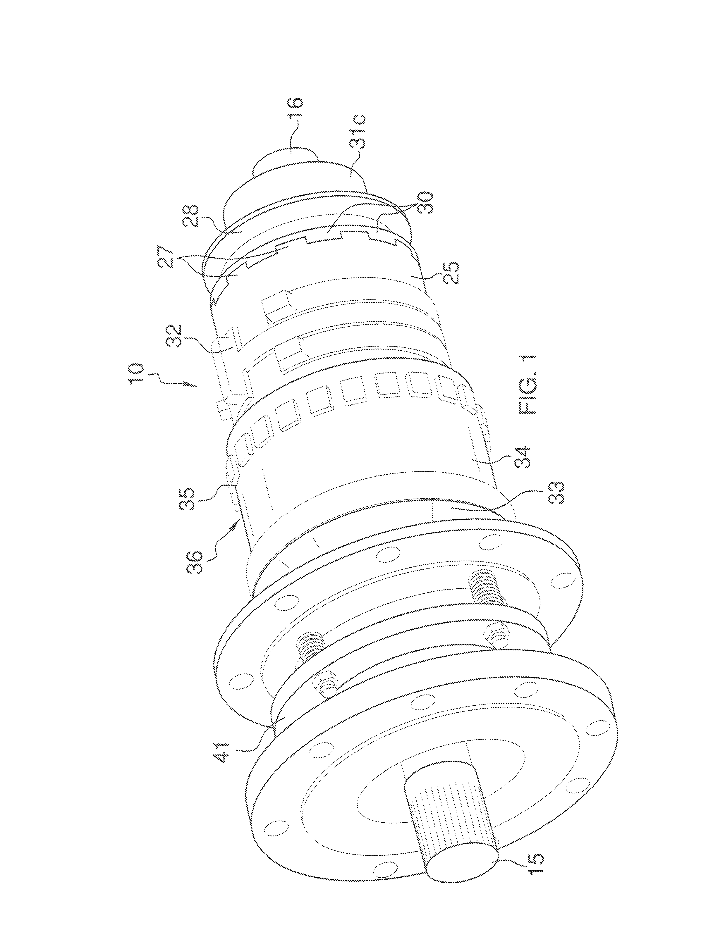
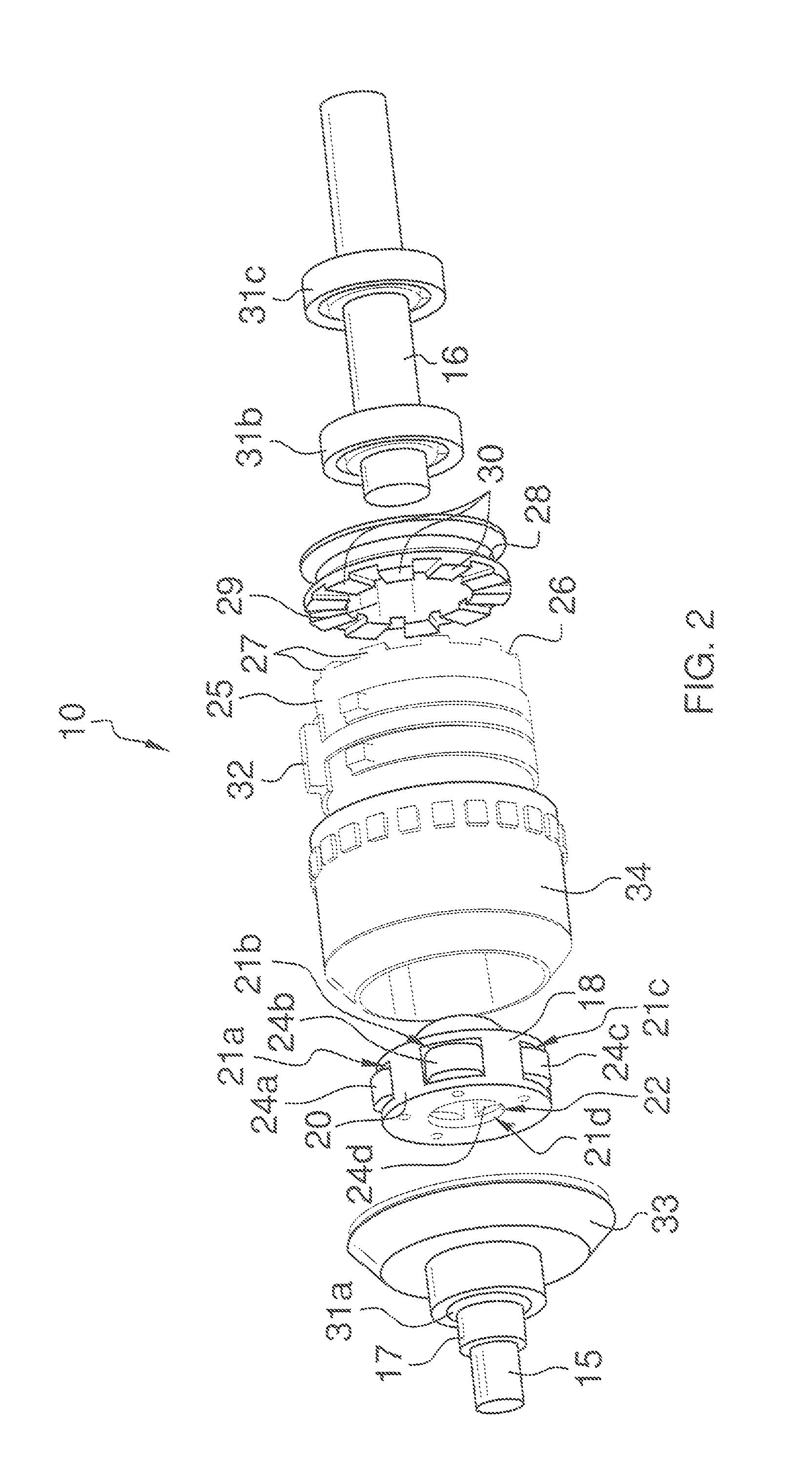
[0020]With reference now to the drawings, and in particular to FIGS. 1 through 5 thereof, a new mechanical power transmission system embodying the principles and concepts of the present invention and generally designated by the reference numeral 10 will be described.

[0021]As best illustrated in FIGS. 1 through 5, the mechanical power transmission system 10 generally comprises a case 11, rotational members 15,16 extending into the case 11, a gear set 17, 18, 24a-d, 25 being in operable communication and conventionally connected to at least one of the rotational members 15,16 and being disposed in the case 11, and a clutch means being movably engagable to the gear set 17, 24a-d, 25 and including fluid from an external fluid source 50 for effecting various speeds. The gear set 17, 24a-d, 25 includes a first gear 17 being in operable communication and conventionally connected to one of the rotational members 15,16. The rotational members 15,16 include a first rotational member 15. The f...


PUM


Abstract

A mechanical power transmission system for transforming and delivering power effectively and efficiently using external pressure to propel a vehicle. The mechanical power transmission system includes a case; rotational members; a gear set being in operable communication to at least one of the rotational members; and a clutch system being in operable communication to the gear set and using external fluid pressure from a fluid source to effectively change speeds.

Description

BACKGROUND OF THE INVENTION[0001]1. Field of the Invention[0002]The present invention relates to power transfer systems and more particularly pertains to a new mechanical power transmission system for transforming and delivering power effectively and efficiently using external pressure to propel a vehicle.[0003]2. Description of the Prior Art[0004]The use of power transfer systems is known in the prior art. More specifically, power transfer systems heretofore devised and utilized are known to consist basically of familiar, expected and obvious structural configurations, notwithstanding the myriad of designs encompassed by the crowded prior art which have been developed for the fulfillment of countless objectives and requirements.[0005]The prior art includes transmissions comprising input and output shafts and also gear sets being in operable communication with the gear sets and clutches including friction plates with fluid from within the case being used to apply the clutch friction...

Claims


Application Information

Patent Timeline
IPC IPC(8): F16H3/44
CPCF16D25/08F16H3/54F16D25/082F16D11/04
Inventor BROOKINS, ERNIE
Owner BROOKINS ERNIE
Why Eureka
Try Eureka