Modular joint prosthesis

a technology of modular joints and joints, applied in the field of modular joints, can solve the problems of not having such modularity of connecting elements, inability to adjust length and angular position, and plurality of prostheses, so as to improve the adaptability of angular position, increase the modularity of prostheses, and increase the length variability

Active Publication Date: 2013-08-27
MERETE MEDICAL
View PDF51 Cites 6 Cited by
  • Summary
  • Abstract
  • Description
  • Claims
  • Application Information

AI Technical Summary

Benefits of technology

[0010]In light of this prior art, the invention is based on the object to provide a modular joint prosthesis which increases the modularity of the prosthesis by increased length variability, allows an improved adjustability of the angular position while, at the same time, reducing the number of parts, and simplifies revision surgeries.
[0023]In a further configuration of the invention, all parts of the joint prosthesis according to the invention have a rough surface to accelerate the ingrowth of the prosthesis in the surgically treated region.

Problems solved by technology

This known prior art has the disadvantage that the prosthesis consists of a plurality of individual parts which requires a sustainable stock-keeping of these parts.
This known teaching might be modularly designed for differently long shafts and sleeves; however, the connecting element itself does not have such modularity.
The fundamental disadvantage of all these known prostheses is that their lengths and angular positions are not adjustable whereby the modularity is significantly limited.
Furthermore, said known prosthesis system has the disadvantage that during a later revision, significant problems can occur when detaching the connecting means which act exclusively in the axial direction because the axial connecting means can only be axially detached and removed which, in turn, can entail an undesired extension of soft, muscle and tendon parts with associated traumatization.

Method used


Image

  • Modular joint prosthesis
  • Modular joint prosthesis
  • Modular joint prosthesis

Examples


example 1

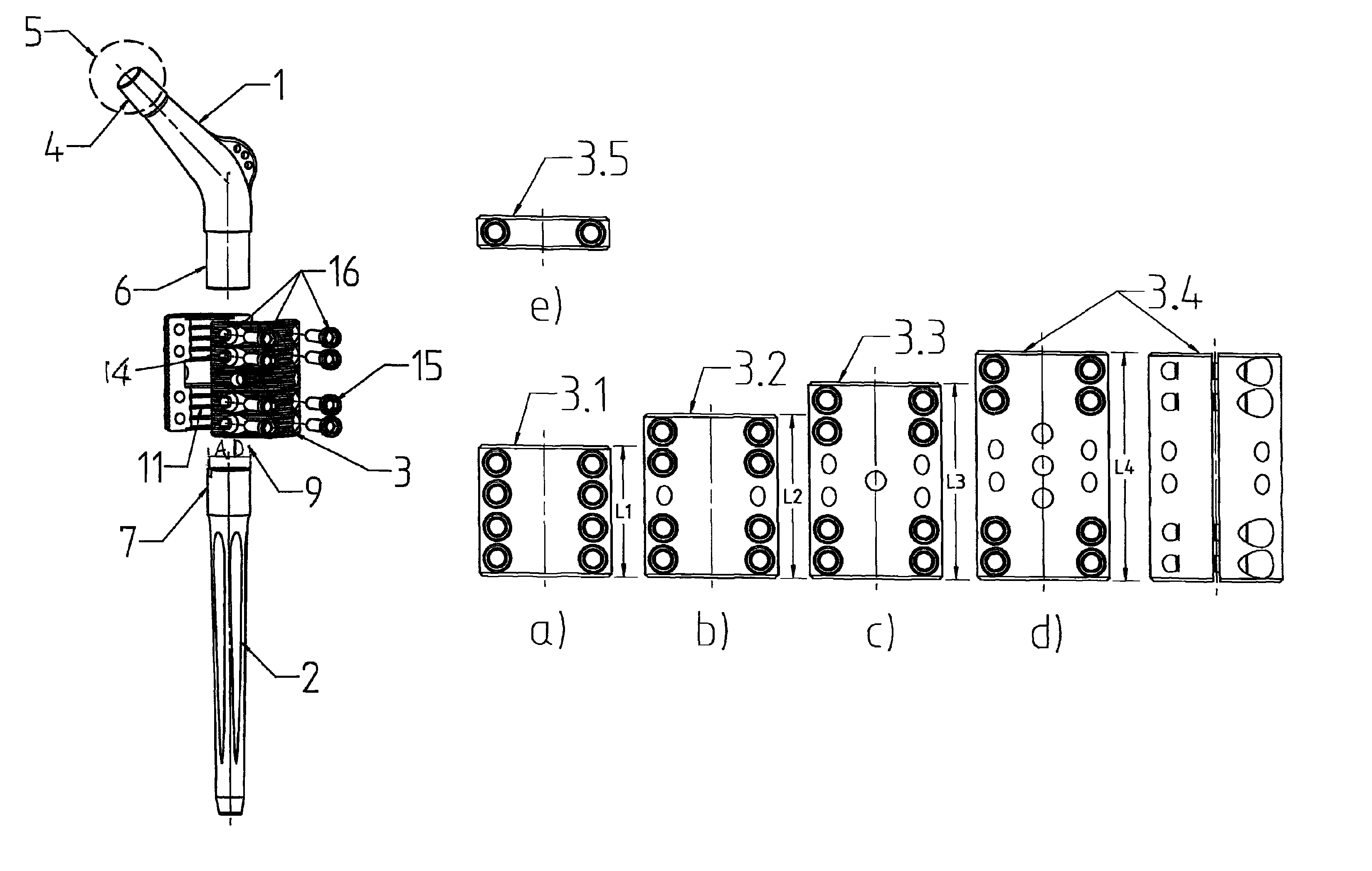
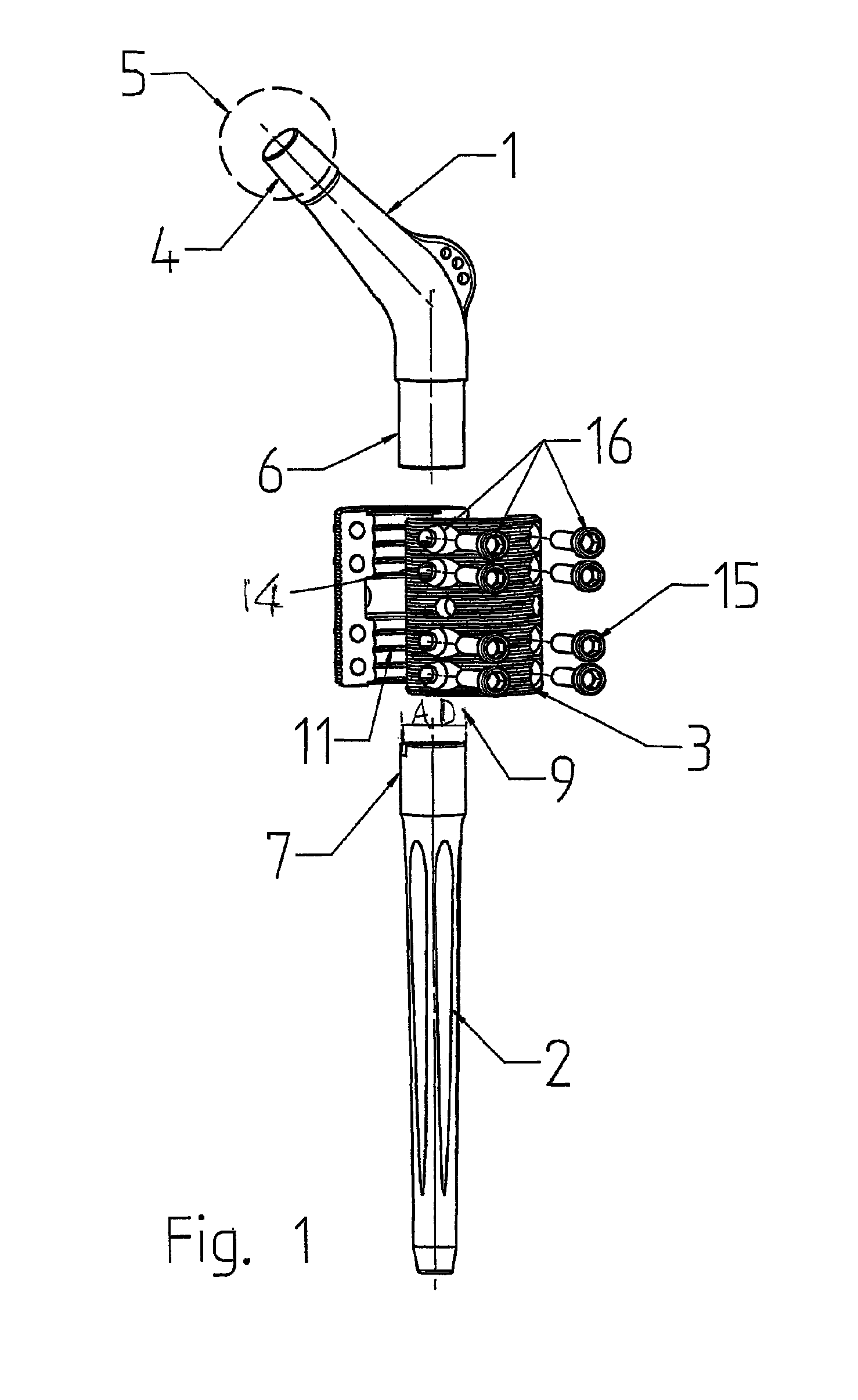
[0036]FIG. 1 shows the basic structure of the joint prosthesis according to the invention in a first embodiment variant in an exploded illustration. The joint prosthesis according to the invention which is used, for example, in case of resections due to metastases in the bone, hip revisions or also in case of infections or trauma, is composed of a curved, one-piece head part 1 which is adapted according to the biomechanical conditions of the anatomy of the respective patient, a nail 2, for example femur nail, and a connection module 3. On the conical pin 4 of the head part 1, a slip-on joint ball 5 is arranged which engages with a non-illustrated joint socket. The distal end of the head part 1 is formed into a cylindrical shaft 6 from solid metal and is inserted into the connection module 3, which is described later, to be fastened therein.

[0037]The nail 2 is inserted into the bone marrow canal of the non-illustrated long bone and anchored therein. The nails 2 have different lengths...

example 2

[0046]FIG. 6 shows a further variant of the joint prosthesis according to the invention in an exploded illustration. This joint prosthesis comprises a shaft-like neck piece 19 of relatively short length and a nail 2, for example femur nail. The essence of this variant of the invention is that the connection module 3, which in example 1 is still a separate part, becomes an integral part of the shaft-like neck piece 19 so that a total of only two elements form the joint prosthesis according to the invention.

[0047]As in example 1, the neck piece 19 has a conical pin 4 onto which a slip-on joint ball 5 is arranged which engages with a non-illustrated joint socket. The distal end of the neck piece 19 is formed into a helmet-like receiving head 20 which has an insertion opening 21 for inserting the nail neck 7. The receiving head 20 is provided with a slot 23 which runs in the direction of the longitudinal axis LA of the head part 19 approximately as far as into the shaft 22 of the neck p...


PUM


Abstract

The invention relates to modular joint prostheses, comprising a curved head part to the conical pins of which a slip-on joint ball is attached, and comprising a nail which can be inserted into the bone marrow canal of the long bone and has a nail neck, wherein a connecting means is provided between the head part and the nail neck which holds the head part in a non-rotatable manner. The connecting means comprises at least one collar-like module which is located in the axial direction of the nail and has at least two semi-shells, which are divided in the axial direction of the module, are detachably connected to each other, form an axially extending passage for inserting the nail head into the passage and have recesses for receiving a tensioning means, which in the tensioned state fixes the nail head in the passage exclusively by way of factional engagement.

Description

CROSS-REFERENCE TO RELATED APPLICATIONS[0001]This application is the U.S. national stage application of International Application No. PCT / DE2009 / 001272, filed Sep. 11, 2009, which International application was published on Apr. 1, 2010 as International Publication No. WO 2010 / 034284 A1 in the German language and which application is incorporated herein by reference. The International application claims priority of German Patent Application No. 10 2008 049 123.3, filed Sep. 26, 2008, which application is incorporated herein by reference.[0002]The invention relates to a modular joint prosthesis having a curved head part, to the conical pin of which a slip-on joint ball is attached, and having a nail which can be inserted into the bone marrow canal of the long bone and has a nail neck, wherein between head part and nail neck a connecting means is provided which holds the head part in a non-rotatable manner.[0003]The invention relates further to a modular joint prosthesis having a shaft...

Claims


Application Information

Patent Timeline
Patent Type & Authority Patents(United States)
IPC IPC(8): A61F2/32
CPCA61F2/36A61F2/30A61F2002/30331A61F2002/30497A61F2002/30604A61F2002/30616A61F2002/3674A61F2220/0025A61F2220/0033A61F2002/30495
Inventor ANAPLIOTIS, EMMANUELKRANZ, CURTHILSE, MARTINLOB, GUNTER
Owner MERETE MEDICAL
Why Eureka
Try Eureka