

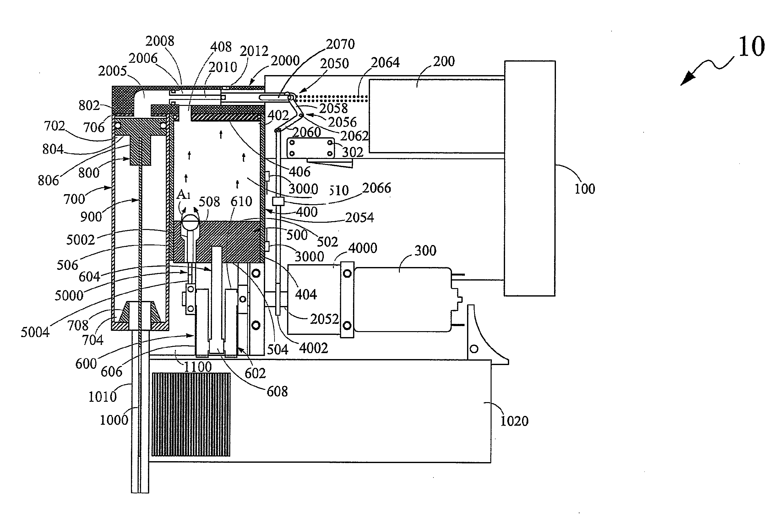
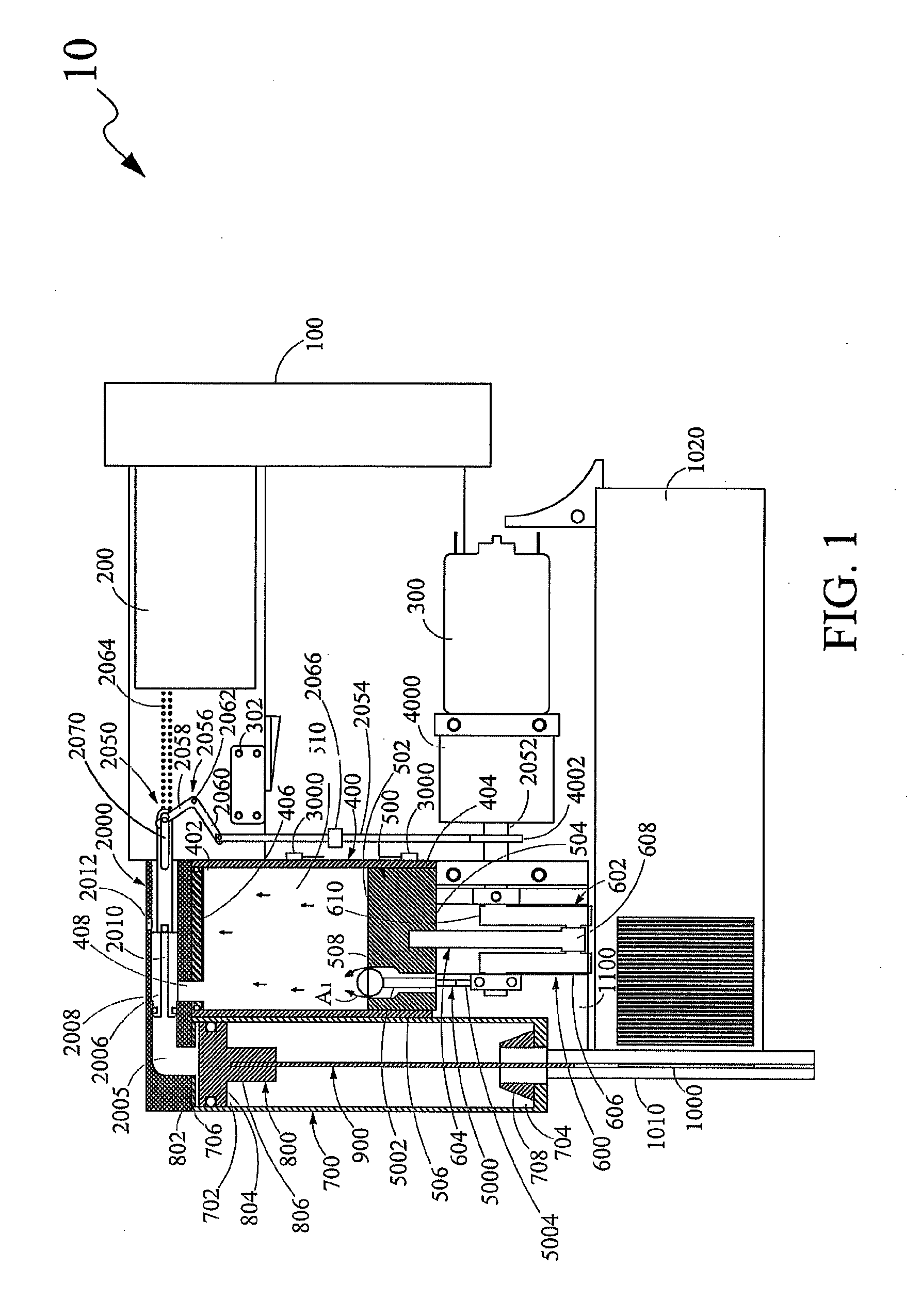
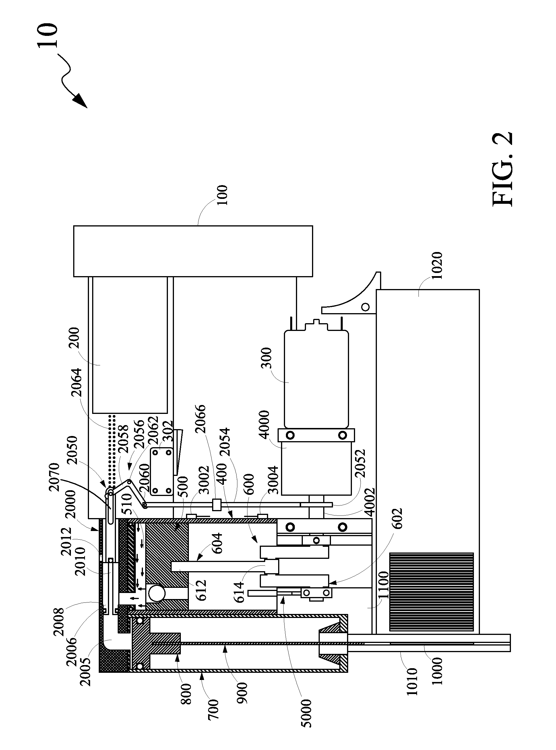
Fastener driving apparatus
a technology for fasteners and driving apparatuses, which is applied in the direction of manufacturing tools, stapling tools, nailing tools, etc., can solve the problems of increased cost, increased labor, and increased cost of users, so as to facilitate the full driving of the fastener into the workpiece, prevent the consumption of drive energy and reduce the drive speed. , the effect of facilitating the effect of the fastener being fully driven into the workpi
- Summary
- Abstract
- Description
- Claims
- Application Information
AI Technical Summary
Benefits of technology
Problems solved by technology
Method used
Image

Examples
Embodiment Construction
[0033]The exemplary embodiments described herein detail for illustrative purposes are subject to many variations in structure and design. It should be emphasized, however, that the present disclosure is not limited to a particular fastener driving apparatus as shown and described. It is understood that various omissions and substitutions of equivalents are contemplated as circumstances may suggest or render expedient, but these are intended to cover the application or implementation without departing from the spirit or scope of the claims of the present disclosure.
[0034]The terms “first,”“second,” and the like, herein do not denote any order, quantity, or importance, but rather are used to distinguish one element from another, and the terms “a” and “an” herein do not denote a limitation of quantity, but rather denote the presence of at least one of the referenced item.
[0035]The present disclosure provides a fastener driving apparatus for driving fasteners into a workpiece. As used h...
PUM
| Property | Measurement | Unit |
|---|---|---|
| lengths | aaaaa | aaaaa |
| volume | aaaaa | aaaaa |
| volume | aaaaa | aaaaa |
Abstract
Description
Claims
Application Information