Electrical feed-through for hermetic compressors

a technology of electric feed-through and compressor, which is applied in the direction of feed-through capacitors, capacitors, anti-noise capacitors, etc., can solve the problems of pressure tightness, difficult maintenance of tolerances in the mounting or connecting position, etc., to achieve cost-effective design, sealing, and improve the effect of sealing

a technology of electric feed-through and compressor, which is applied in the direction of feed-through capacitors, capacitors, anti-noise capacitors, etc., can solve the problems of pressure tightness, difficult maintenance of tolerances in the mounting or connecting position, etc., to achieve cost-effective design, sealing, and improve the effect of sealing

US8525047B2Active Publication Date: 2013-09-03HANON SYST

Image

  • Electrical feed-through for hermetic compressors
  • Electrical feed-through for hermetic compressors
  • Electrical feed-through for hermetic compressors

Examples


Embodiment Construction

[0036]The following detailed description and appended drawings describe and illustrate various embodiments of the invention. The description and drawings serve to enable one skilled in the art to make and use the invention, and are not intended to limit the scope of the invention in any manner. In respect of the methods disclosed, the steps presented are exemplary in nature, and thus, the order of the steps is not necessary or critical.

[0037]In the following, an embodiment of the pressure-tight, insulating conductor feed-through will be described in greater detail:

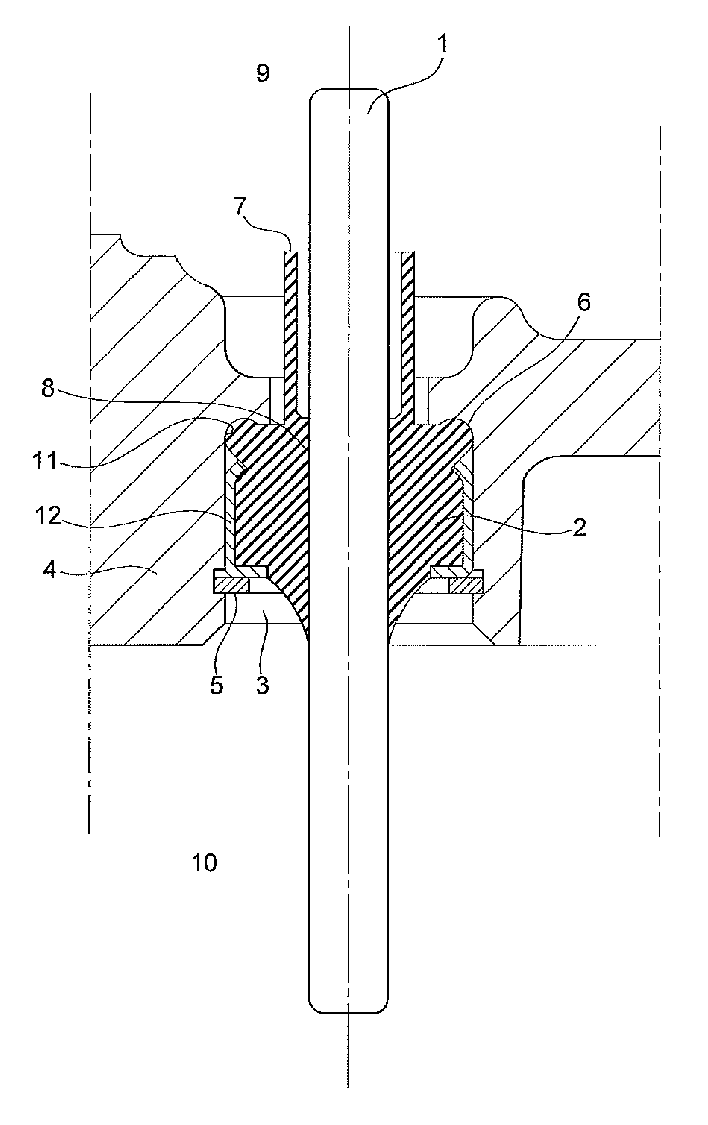
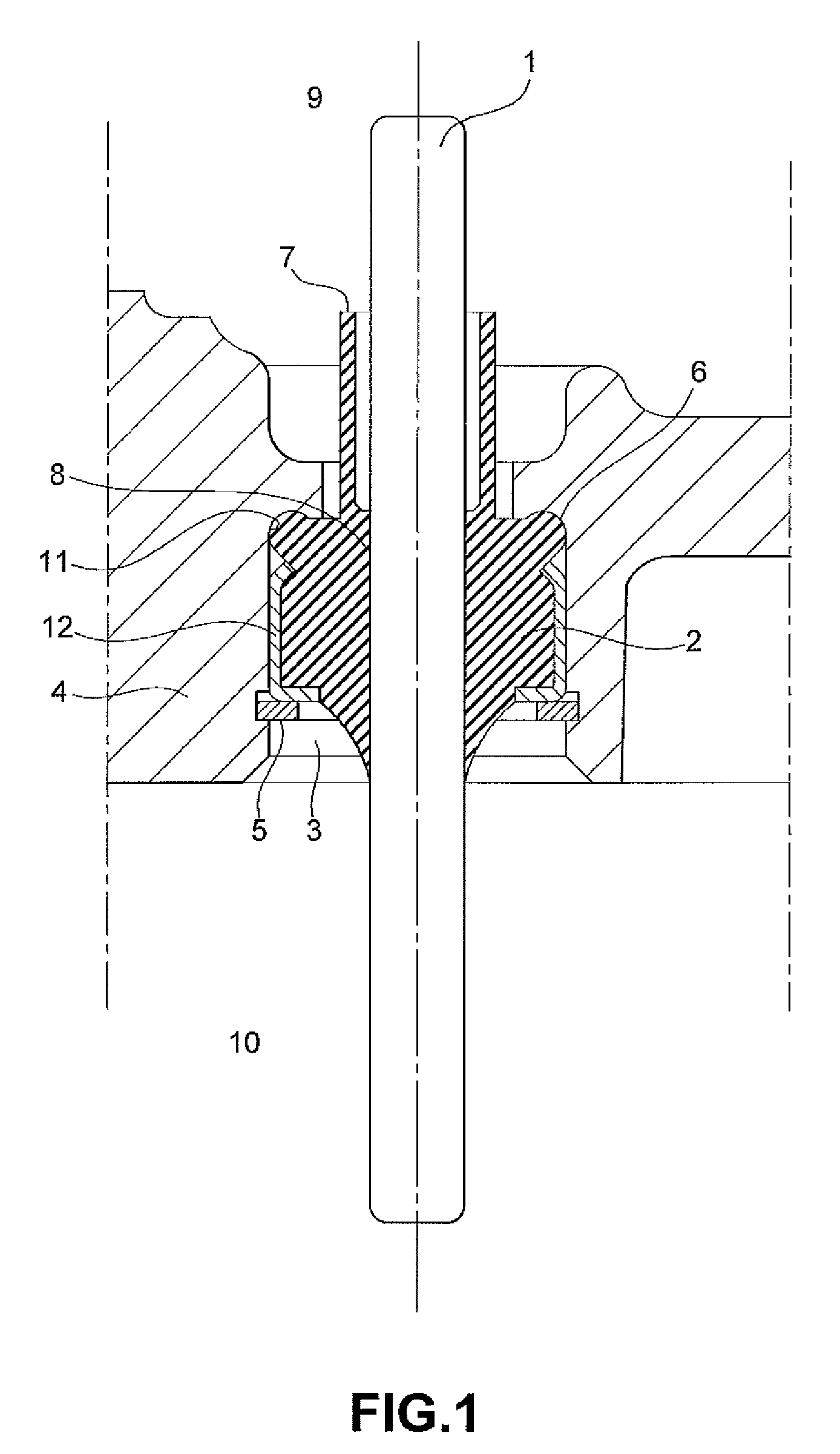
[0038]FIG. 1 shows the conductor feed-through for a hermetic compressor passing through a casing 4 of the hermetic compressor.

[0039]In the casing 4, there is an opening 3 through which the electric connection pin 1 for the electrically driven HVAC compressor (not shown) is passed with an insulation member 2.

[0040]The connection pin 1 is connected by a chemical-physical connection of the materials along a connection region ...


PUM


Abstract

An electrical feed-through includes an electrically conductive connection pin and an elastic insulation member coupled to the connection pin by vulcanizing the insulation member, wherein the coupled connection pin and insulation member are arranged in an opening of a casing and pressure-tightly clamped in the opening by a fastening element.

Description

CROSS-REFERENCE TO RELATED APPLICATION[0001]The present application claims priority to German Patent Application Serial Number DE 102010001381.1 filed Jan. 29, 2010 and German Patent Application Serial No. 102010043773.5 filed Nov. 11, 2010, the entire disclosures of which are hereby incorporated herein by reference.FIELD OF THE INVENTION[0002]The invention relates to a pressure-tight, electrically insulating feed-through for an electric connection, the feed-through particularly usable for hermetic compressors in refrigerant circuits.BACKGROUND OF THE INVENTION[0003]In hermetic compressors, the problem exists of an electric connection and an accompanied electrical feed-through leading through a casing of the hermetic compressor combined with the problem of pressure tightness of the feed-through, as there is a pressure difference between an interior of the casing and an outside environment.[0004]Therefore, appropriately pressure-tight feed-throughs, which at the same time electricall...

Claims


Application Information

Patent Timeline
03 Sep 2013
Publication
US8525047B2
IPC
H02G3/18
CPC
H02G3/22; H02G3/088
Inventors
GUNTERMANN, BERND; ALBERTERNST, THOMAS