Illumination devices for image acquisition systems

an image acquisition and image technology, applied in the field of image acquisition systems, can solve the problems of inability to distinguish image features, inability to accurately illuminate high-angle bright fields, and inability to achieve uniform illumination, etc., to achieve selective color illumination, reduce optical components, and cost effective

Inactive Publication Date: 2011-09-13
COGNEX CORP
View PDF29 Cites 12 Cited by
  • Summary
  • Abstract
  • Description
  • Claims
  • Application Information

AI Technical Summary

Benefits of technology

[0015]An advantage of the present invention is that it provides optical detection systems, such as ID or symbology readers, which have more uniform bright field illumination and / or dark field illumination.
[0016]Another advantage of the present invention is that it provides a diffuse (uniform, non-directed, cloudy day) type illumination which can advantageously be use to read dark marks, on highly polished surfaces such as laser or chemically etched, or inkjet codes on polished cylindrical rods, sheets of metal, or semiconductor wafers, and other markings and characteristics.
[0017]Yet another advantage of the present invention is that it provides optical detection systems, such as ID or symbology readers, which have fewer optical components.
[0018]Yet another advantage of the present invention is that it provides a more cost effective design for optical detection systems.
[0019]Yet another advantage of the present invention is that it can provide selective color illumination.
[0020]Yet another advantage of the present invention is that it can easily be adapted to either handheld or fixed mount readers.

Problems solved by technology

When a symbol or mark is etched or peened onto a surface of a part or a component and the surface of the part or component is rough or irregular, high-angle bright field illumination may not be appropriate.
To this end, irregular surfaces of mark features tend to scatter as much light back to the reader as the surface to which the mark is applied, resulting in indistinguishable features in the image.
First, intensity differences between LEDs have been known to create non-uniformities in the illumination.
Second, known systems require multiple LED sets and / or additional optics, such as light pipes, reflectors and diffusers.
Third, in the case of the bright field illumination, the diffuser absorbs some of the light, thereby reducing the brightness of the light applied to the marked surface.
Fourth, in the case of the bright field illumination, the LEDs are off the optical axis of the reflector, which can also create non-uniformities in the illumination.

Method used


Image

  • Illumination devices for image acquisition systems
  • Illumination devices for image acquisition systems
  • Illumination devices for image acquisition systems

Examples


Embodiment Construction

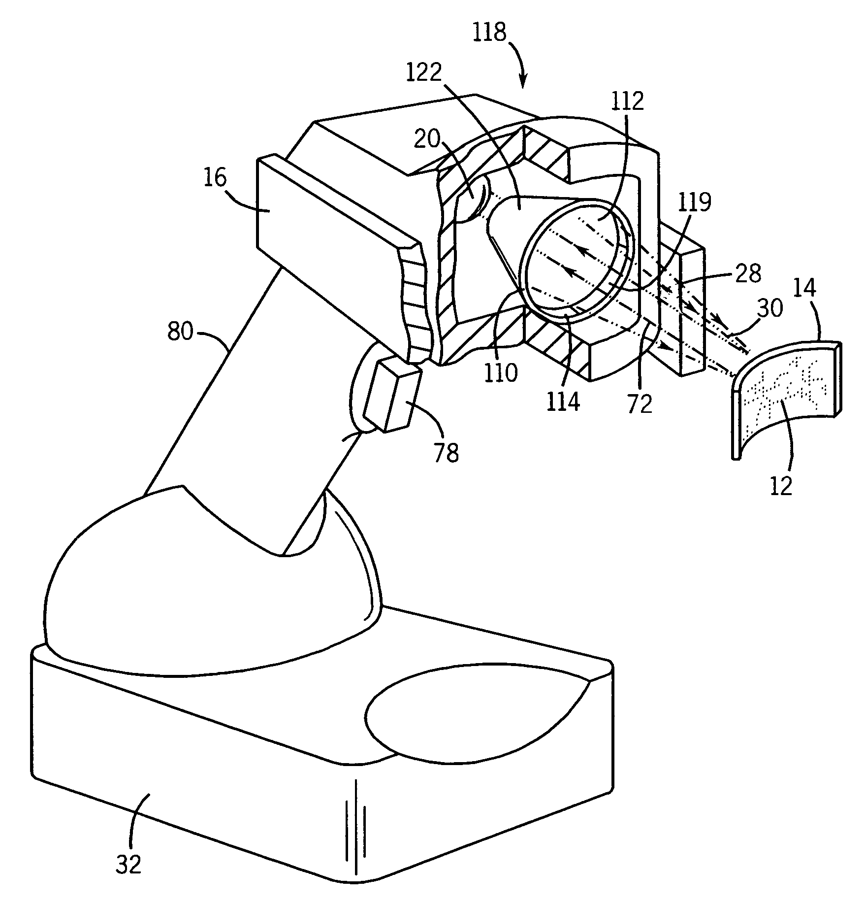
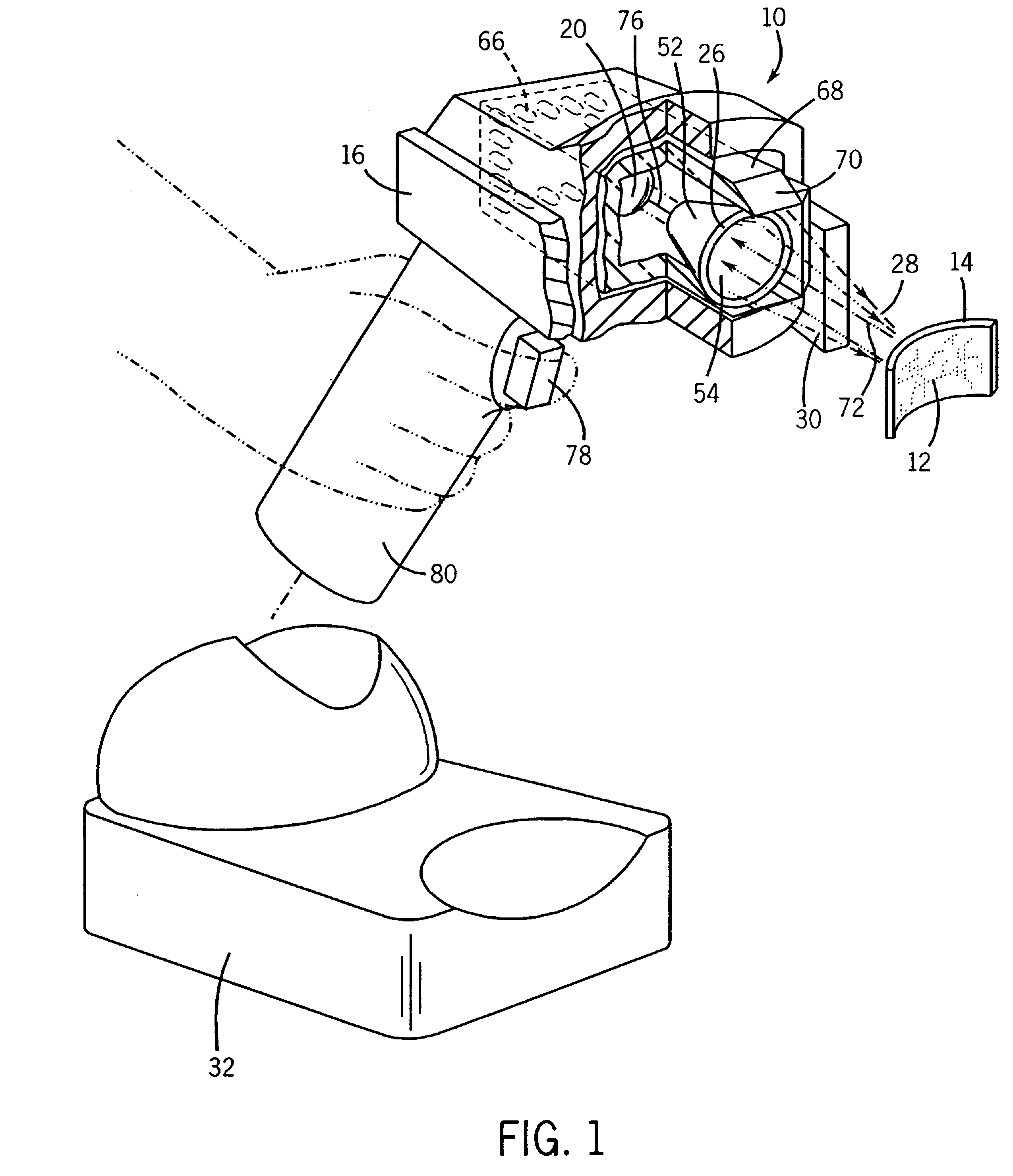
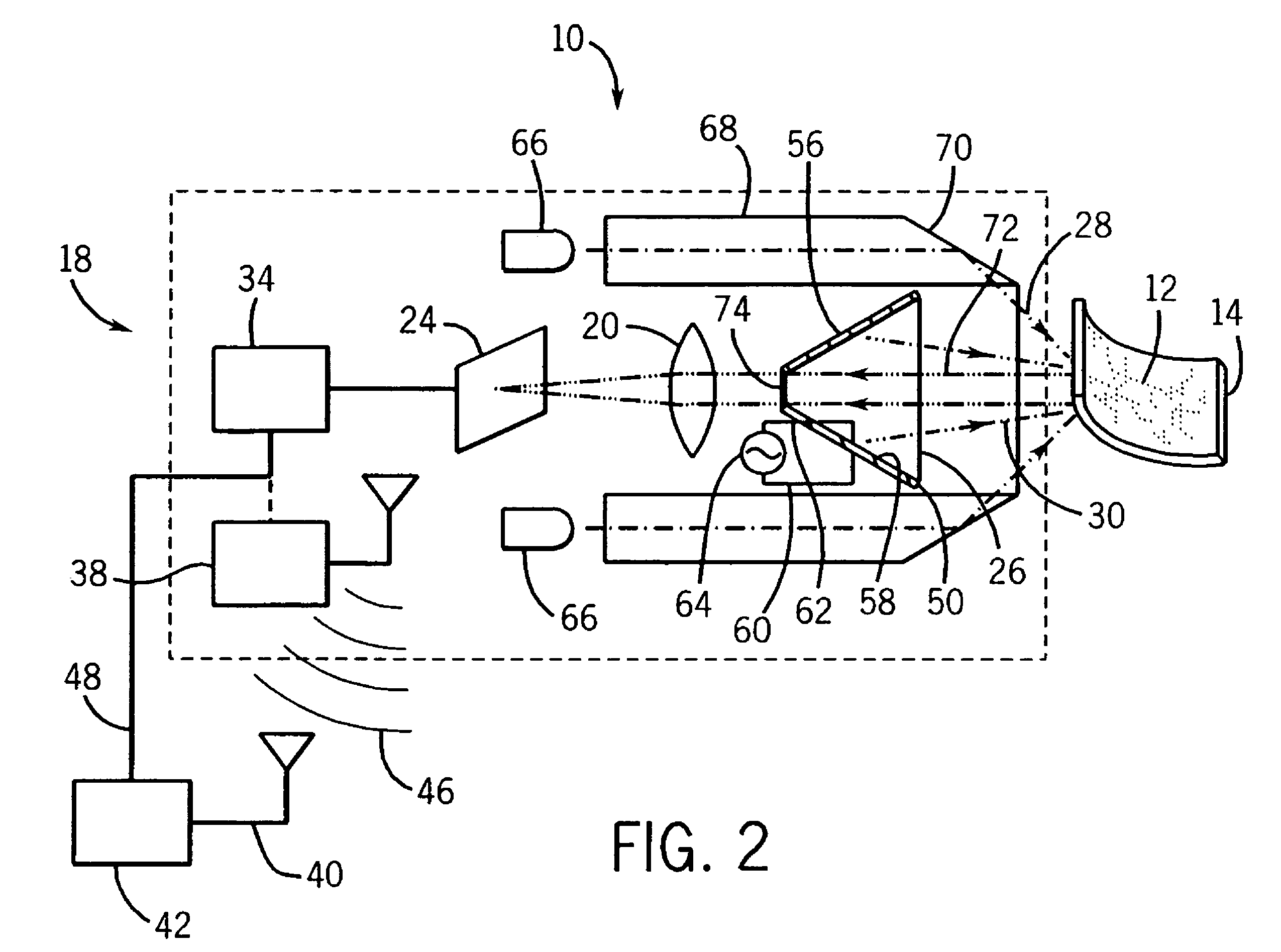
[0035]Referring now to the drawings, and more particularly to FIGS. 1 and 2, there is shown an apparatus 10 for imaging a symbol or characteristic 12 on an object 14 which generally includes a housing 16, an imaging or detection module 18 connected to housing 16, where imaging module 18 includes at least one lens 20 for creating an image of symbol 12, and a sensor 24 for sensing the image. Apparatus 10 further includes an electroluminescent light panel or sheet 26 connected to housing 16, where electroluminescent light sheet 26 provides dark field illumination 28 and / or bright field illumination 30. Electroluminescent light sheet 26, and other electroluminescent light sheets described below, can provide an extended diffuse (uniform, non-directed, cloudy day) type illumination which can advantageously be use to read dark marks, on highly polished surfaces such as laser or chemically etched, or inkjet codes on polished cylindrical rods, sheets of metal, or semiconductor wafers, among ...


PUM


Abstract

An apparatus for imaging a symbol associated with an object which includes a housing and an imaging module connected to the housing, where the imaging module includes at least one lens for creating an image of the symbol. The imaging module further has a sensor for sensing the image. An electroluminescent light sheet is connected to the housing, and the electroluminescent light sheet provides at least one of dark field illumination and bright field illumination.

Description

CROSS-REFERENCE TO RELATED APPLICATION[0001]Not applicable.STATEMENT CONCERNING FEDERALLY SPONSORED RESEARCH OR DEVELOPMENT[0002]Not applicable.FIELD OF THE INVENTION[0003]The present invention relates to illumination devices for image acquisition systems, and more particularly, to illumination devices for image acquisition systems used for reading identification codes.BACKGROUND OF THE INVENTION[0004]Machine vision sensors and identification (ID) readers are used for reading printed and direct part mark (DPM) codes for manufacturers implementing part traceability programs in the automotive, aerospace, electronics, healthcare, defense, and other industries and for other applications such as quality control during production of a product, supply chain processes and end use applications. Exemplary ID codes include 1-D barcodes and 2-D codes Code 128, Code 39, UPC, EAN, interleaved 2 of 5, and QR Code. The rapid adoption of DPM codes and other identification for part traceability has m...

Claims


Application Information

Patent Timeline
Patent Type & Authority Patents(United States)
IPC IPC(8): G06K7/10
CPCG06K7/10732
Inventor NUNNINK, LAURENS
Owner COGNEX CORP
Why Eureka
Try Eureka