Steering arm

a technology of steering arm and steering linkage, which is applied in the direction of steering linkage, steering parts, vehicle components, etc., can solve the problems of reducing the effectiveness of the prior art configuration, presenting an offset load, and excessive use of arms, so as to reduce the amount of material, cost effective, and the effect of reducing the amount of material

Inactive Publication Date: 2007-11-29
ARVINMERITOR TECH
View PDF7 Cites 15 Cited by
  • Summary
  • Abstract
  • Description
  • Claims
  • Application Information

AI Technical Summary

Benefits of technology

[0006]This cross-sectional configuration significantly reduces the amount of material required to form the steering arm, which provides a more cost effective design. Further, the I-shaped section will experience equivalent stress as compared to prior trapezoidal designs under maximum loading conditions.

Problems solved by technology

The load of the steering arm is applied through a center of the ball stud at the drag link, which presents an offset load.
The cross-section of 10 in the prior art is not oriented or “clocked” optimally to meet this offset loading, thus further reducing the effectiveness of the prior art configuration.
Further, these traditional hook style steering arms use excessive material to ensure a robust design.

Method used


Image

  • Steering arm
  • Steering arm
  • Steering arm

Examples


Embodiment Construction

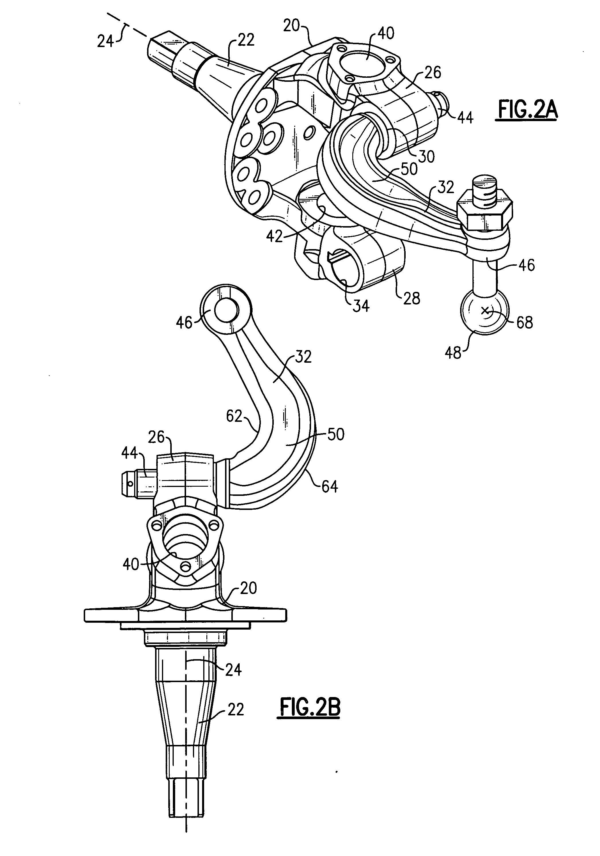
[0013]FIGS. 2A and 2B show a knuckle 20 for a vehicle wheel assembly (not shown). The knuckle 20 includes a spindle 22 that supports a vehicle wheel assembly for rotation about an axis 24. The knuckle 20 includes an upper boss portion 26 and a lower boss portion 28. The upper boss portion 26 includes a steering arm bore 30 that receives a steering arm 32. The lower boss portion 28 includes a tie rod arm bore 34 that receives a tie rod arm (not shown).

[0014]The upper boss portion 26 includes an upper bore 40 and the lower boss portion 28 includes a lower bore 42. A king pin (not shown) is inserted through the upper 40 and lower 42 bores as known. The upper 40 and lower 42 bores extend in a generally vertical direction, while the steering arm 30 and tie rod arm 34 bores extend in a generally horizontal direction.

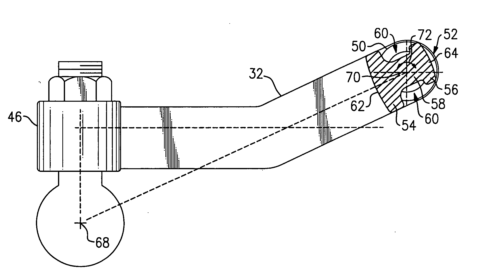
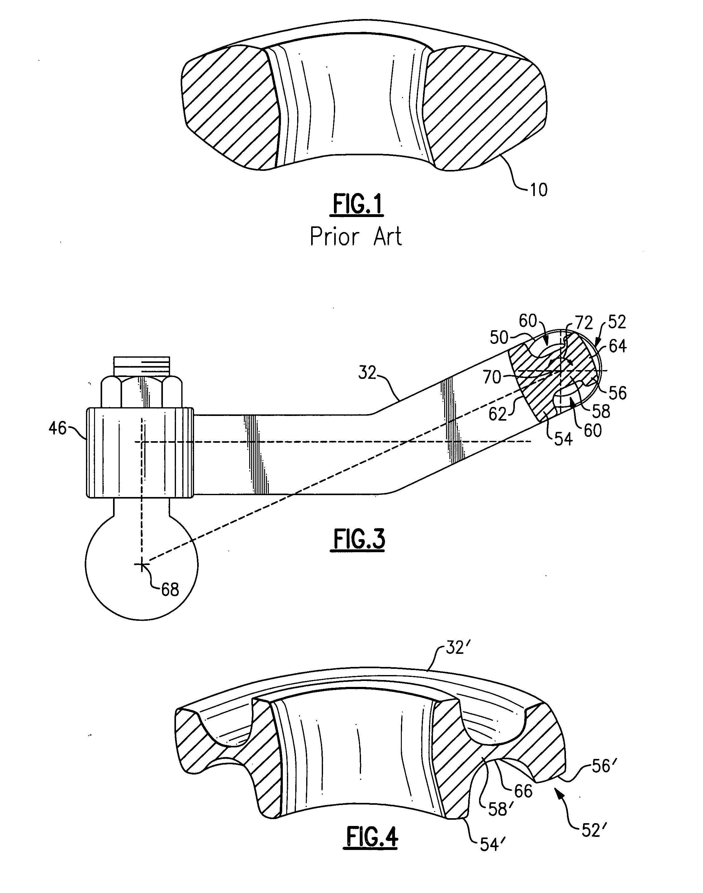
[0015]The steering arm 32 includes a first end 44 that is connected to the knuckle 20 at the steering arm bore 30 and a second end 46 that is connected to a drag link (not sho...


PUM


Abstract

A steering arm includes a curved center portion having a recessed area where the curved center portion is defined by a non-symmetrical cross-section. The non-symmetrical cross-section comprises an I-section having first and second portions interconnected by a third portion. The first portion has a greater cross-sectional area than the second portion.

Description

TECHNICAL FIELD[0001]The subject invention relates to a reduced weight steering arm for a vehicle steering system that has an I-shaped cross-section that is formed to reduce material stock size required for forging while maintaining original strength of the component.BACKGROUND OF THE INVENTION[0002]A steering arm is used to transmit a steering input from a steering linkage to a vehicle wheel. The steering linkage is comprised of various components, such as a pitman arm, drag link, etc., and is actuated by a steering wheel. One end of the steering arm is connected to a steering knuckle at the vehicle wheel, and an opposite end of the steering arm is connected to the drag link with a ball stud. The steering arm is used to convert a drag link force into a turning moment about a king pin installed within the steering knuckle. The steering arm is subjected to high concentrations of stress during turning maneuvers and is a critical component within a vehicle steering system. Thus, the st...

Claims


Application Information

Patent Timeline
Patent Type & Authority Applications(United States)
IPC IPC(8): B62D7/18
CPCB62D7/20B62D7/18
Inventor STOIA, LUCAS
Owner ARVINMERITOR TECH
Why Eureka
Try Eureka