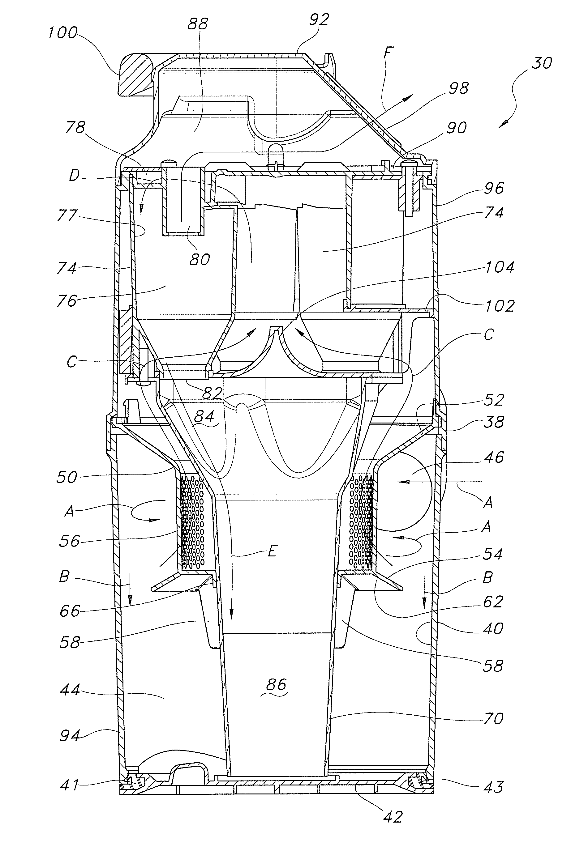
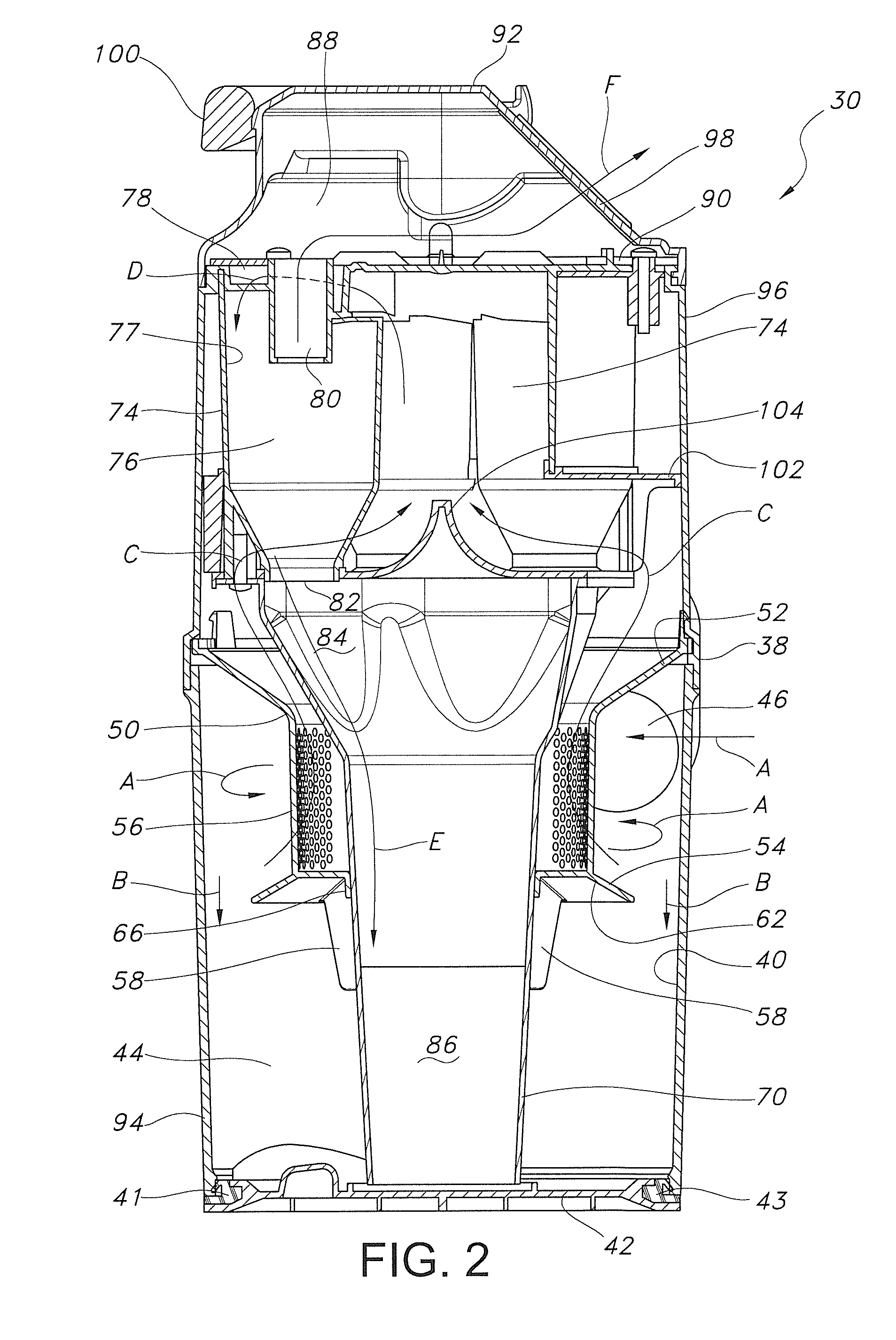
Dirt cup assembly with a pre-filter having a plurality of ribs
a pre-filter and dirt cup technology, applied in the direction of cleaning filter means, separation processes, filtration separation, etc., can solve the problems of reducing the overall cleaning efficiency of the vacuum cleaner, reducing the air turbulence, and placing fins or vanes along the outer sidewall is not the most desirable solution. , to achieve the effect of reducing air turbulen
- Summary
- Abstract
- Description
- Claims
- Application Information
AI Technical Summary
Benefits of technology
Problems solved by technology
Method used
Image

Examples
Embodiment Construction
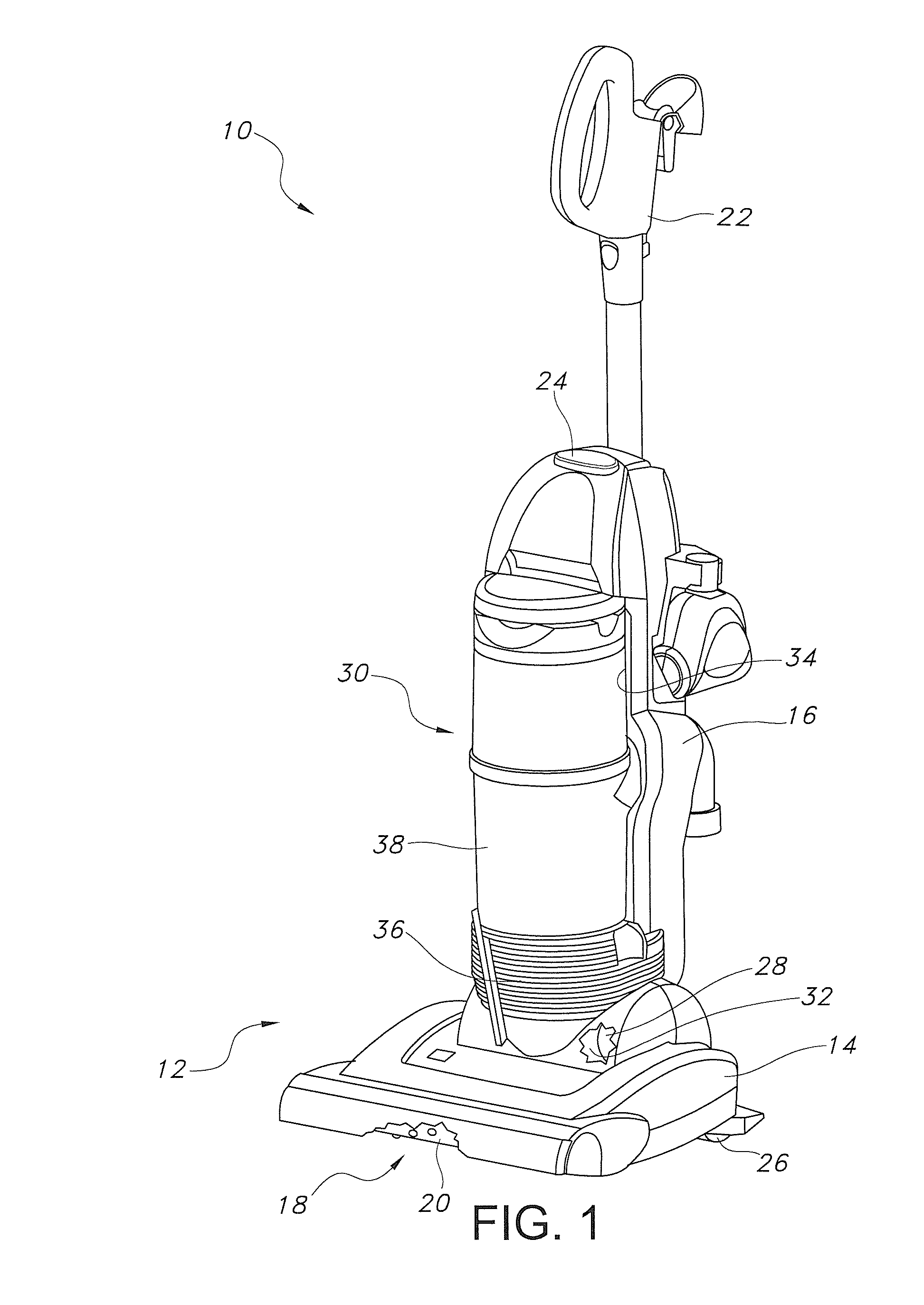
[0020]Reference is now made to FIG. 1 illustrating the floor care apparatus of the present invention in the form of an upright vacuum cleaner 10. The upright vacuum cleaner 10 has a housing 12 comprising a nozzle assembly 14 and a canister assembly 16. As is known in the art, the nozzle assembly 14 and canister assembly 16 are pivotally connected together. Further, the nozzle assembly includes a suction inlet 18. A rotary agitator 20 is mounted on the nozzle assembly 14 adjacent the suction inlet 18. The rotary agitator 20 may be equipped with bristles, tufts, wipers or other projecting cleaning structures (not shown) in a manner known in the art.
[0021]The canister assembly 16 includes an operating handle 22 by which the operator may control the movement of the vacuum cleaner 10 during the cleaning operation. A control switch 24 allows the operator to turn the vacuum cleaner on and off. Wheels 26 provided on the housing 12 allow the vacuum cleaner 10 to be moved smoothly across the ...
PUM
| Property | Measurement | Unit |
|---|---|---|
| centrifugal force | aaaaa | aaaaa |
| force of gravity | aaaaa | aaaaa |
| velocity | aaaaa | aaaaa |
Abstract
Description
Claims
Application Information
 - R&D
- Intellectual Property
- Life Sciences
- Materials
- Tech Scout
- Unparalleled Data Quality
- Higher Quality Content
- 60% Fewer Hallucinations
Browse by: Latest US Patents, China's latest patents, Technical Efficacy Thesaurus, Application Domain, Technology Topic, Popular Technical Reports.
© 2025 PatSnap. All rights reserved.Legal|Privacy policy|Modern Slavery Act Transparency Statement|Sitemap|About US| Contact US: help@patsnap.com