
Mechanical device to assist in the external compression of the chest during cardio-pulmonary resuscitation

a mechanical device and chest compression technology, applied in the field of mechanical devices to assist in the external compression of the chest during cardio-pulmonary resuscitation, can solve the problems of incomplete chest wall recoil, ineffective methods, and inability to save lives, etc., and achieve the effect of simple, effective and economical devices

Inactive Publication Date: 2013-09-17
RAO SUBHAKAR PATTHI
View PDF35 Cites 23 Cited by
  • Summary
  • Abstract
  • Description
  • Claims
  • Application Information

AI Technical Summary

Benefits of technology

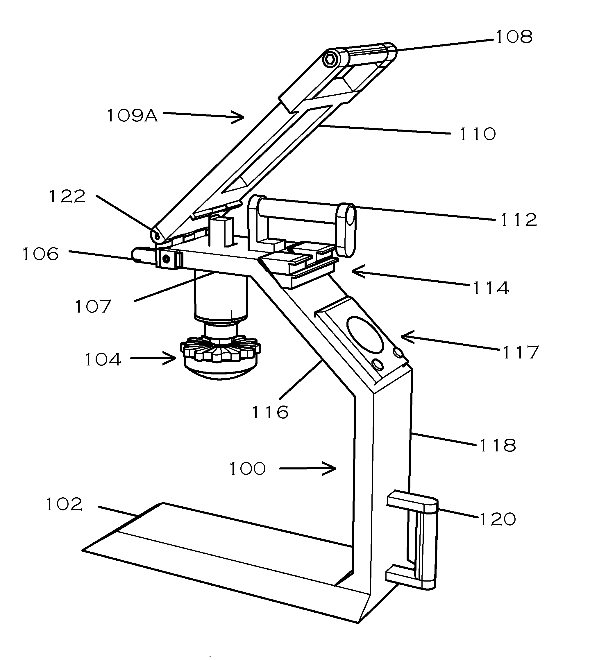
The patent describes a device for performing chest compressions during cardiopulmonary resuscitation (CPR) that is simple, effective, and economical. The device consists of a rigid frame with a top member and bottom member, and a plunger unit that can be compressed repeatedly. The plunger unit has a central hollow plunger with a stem on the top, and a flanged cap that traps the upper end of a coil spring. The bottom member has a handle for exerting downward force on the sternally placed dome to achieve the desired chest compressions. The device can be adjusted to control the depth of the chest compressions and can be motorized for use in emergency situations. The technical effects of the device include its simplicity, effectiveness, and affordability.

Problems solved by technology

Retrospective studies have shown that this method has not been effective in saving lives.
Excessive ventilation, incomplete chest wall recoil, and interruptions in chest compressions in the traditional CPR do not improve the blood flow to the heart, brain etc.
This worsens the chances of survival and increase the possibility of brain damage.
This maneuver may delay the onset of tissue death and extend the brief window of opportunity for a successful resuscitation.
In this configuration there is minimal mechanical advantage and as such early life-saver fatigue is still an issue.

Method used


Image

  • Mechanical device to assist in the external compression of the chest during cardio-pulmonary resuscitation
  • Mechanical device to assist in the external compression of the chest during cardio-pulmonary resuscitation
  • Mechanical device to assist in the external compression of the chest during cardio-pulmonary resuscitation

Examples


Embodiment Construction

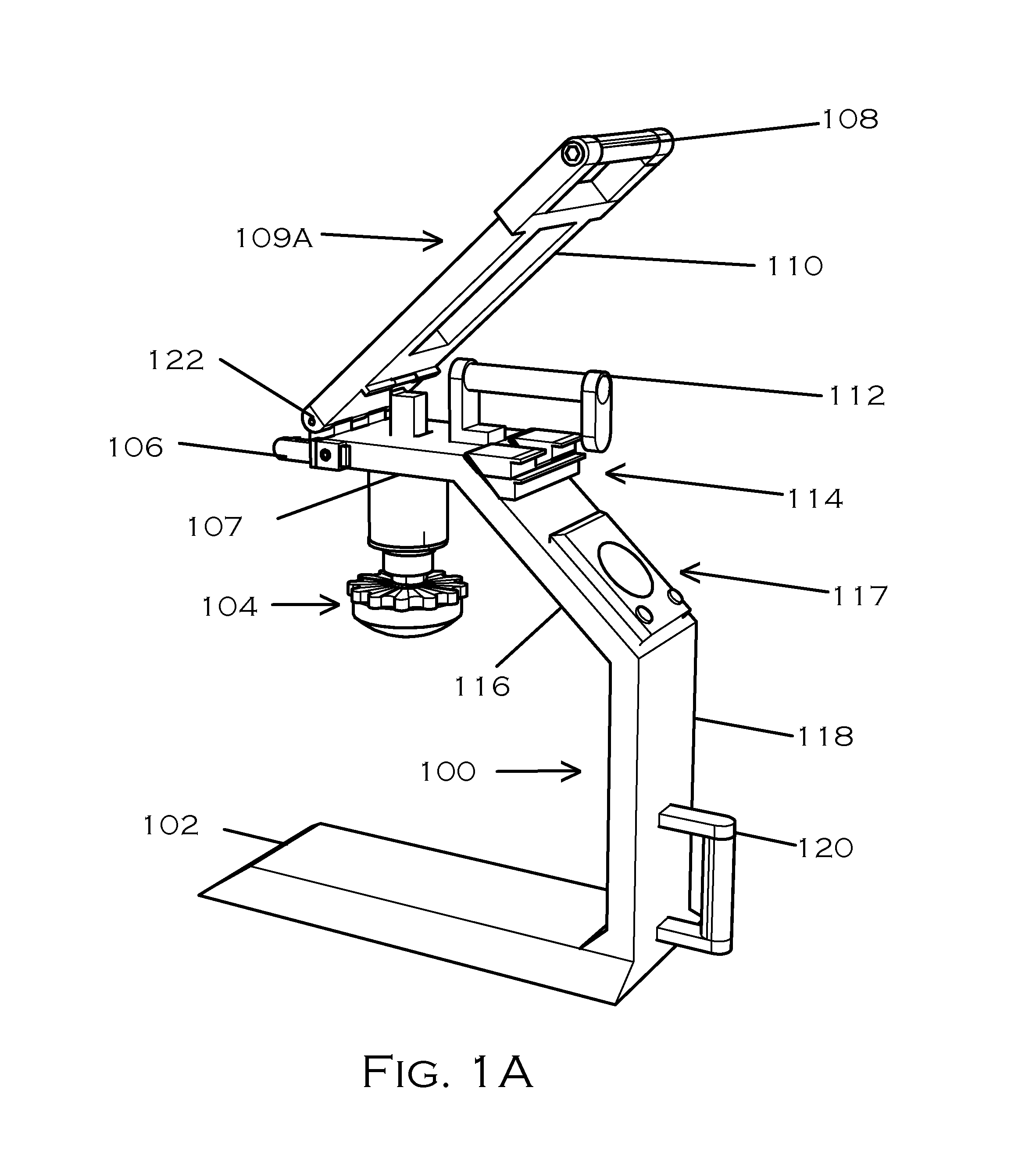
[0094]FIG. 1A shows the embodiment in a perspective view. The primary lever 109A is in an operational position. An optional after market electronic metronome 117 is mounted on the sloping part of the upright member with hook and loop or similar material for ease of removal or servicing the unit. The sections 102, 107, 116, and 118, comprising the rigid frame are permanently fused. The two handles 112 and 120 have non-slip sleeves or a non-slip coating on the cylindrical parts for improved grip. A pair of plunger depth limiting blocks 114 is in an inactive position.

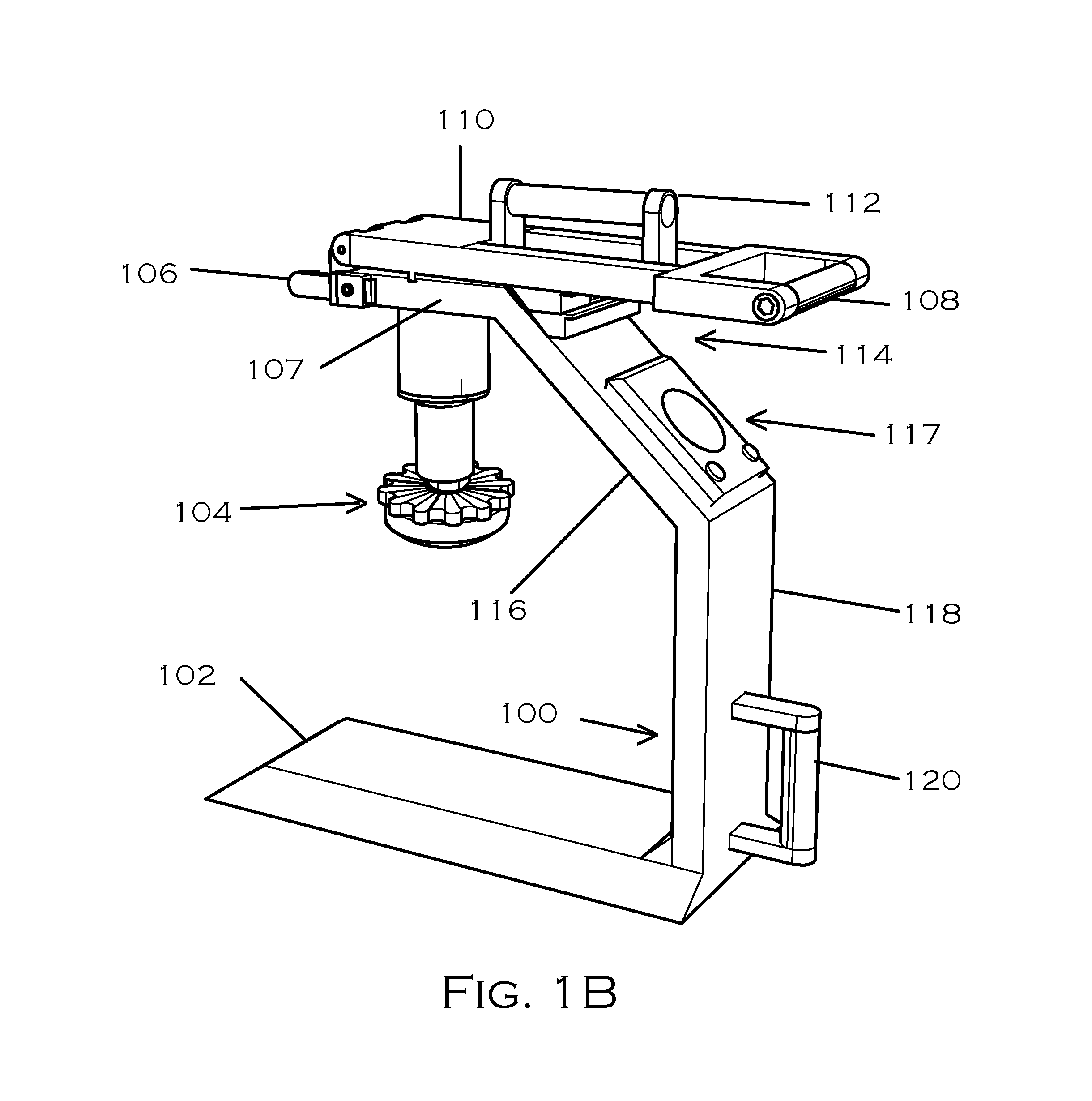
[0095]FIG. 1B shows the same embodiment with the lever 109A in a compressed position wherein the dome of the plunger unit 104 has ventrally traversed the default 2 inches. The carrying handle is seen passing thru the opening in the body 110 of the primary lever 109.

[0096]FIG. 1C shows the same embodiment in a storage position. The lever 109A is rotated cranially to assume a ventrally directed vertical position and is held ...


PUM


Abstract

A portable mechanical device to assist in external chest compressions during cardio-pulmonary resuscitative procedures. The embodiment consists of a frame (100), a plunger unit (104) and an articulating lever (109). The bottom member (102) of the frame is positioned under the subject such that the dome of the plunger unit (104) rests above the mid-sternal region. The handle (108) at the free end of the lever is used to apply downward force by the life-saver to provide the necessary chest compressions. The device is light in weight, easily transportable, and has an indefinite shelf life. This device is designed to be used by anyone with a basic training in CPR. The portability of the device renders itself useful outside the environs of a hospital, in confined quarters, and at remote locations.

Description

BACKGROUNDPrior Art[0001]U.S. Pat. No. 5,184,606 issued to George Csorba on Feb. 9, 1993[0002]U.S. Pat. No. 5,257,619 issued to Randall L. Everette on Nov. 2, 1993[0003]The standard protocol for a ‘Cardiac arrest’ outside the hospital environment has been external chest compressions with intermittent forced mouth-to-mouth respiration till recovery of the subject or the arrival of additional help or with a tragic ending. Retrospective studies have shown that this method has not been effective in saving lives. Excessive ventilation, incomplete chest wall recoil, and interruptions in chest compressions in the traditional CPR do not improve the blood flow to the heart, brain etc. This worsens the chances of survival and increase the possibility of brain damage. New guidelines given by the American Heart Association in 2010 recommends high quality chest compressions to a depth of two inches for an adult and at the rate of 100 per minute in an effort to restore flow of oxygenated blood to...

Claims


Application Information

Patent Timeline
Patent Type & Authority Patents(United States)
IPC IPC(8): A61H31/00A61H31/02
CPCA61H31/007A61H2201/14A61H2201/5048
Inventor RAO, SUBHAKAR PATTHI
Owner RAO SUBHAKAR PATTHI
Learn More