Coating method and coating apparatus

a coating apparatus and coating technology, applied in the direction of coatings, chemistry apparatus and processes, ceramic layered products, etc., to achieve the effects of simple apparatus configuration, high viscosity, and easy operation and maintenan

Inactive Publication Date: 2013-09-17
TORAY IND INC
View PDF22 Cites 3 Cited by
  • Summary
  • Abstract
  • Description
  • Claims
  • Application Information

AI Technical Summary

Benefits of technology

[0042]According to a coating method and a coating apparatus of an embodiment of the present invention, a coating liquid having a high viscosity in comparison to that of the conventional technology can be applied to an upper surface of a running resin film by means of the rod coating method wherein an apparatus configuration is simple and the apparatus is easily operable and maintainable. The high-viscosity coating liquid can be applied without the generation of transverse thickness-difference lines in the in-line coating. Therefore, the coating liquid which was conventionally diluted with an organic solvent to reduce its viscosity can be replaced with a coating liquid which is not diluted with the organic solvent, which decreases a burden imposed on environments.
[0043]Further, a part of the coating process, which was conventionally carried out in the off-line coating where an explosion-proof apparatus was provided because the organic solvent was used, can be carried out in the in-line coating. Thus, manufacturing costs can be reduced. Further, according to another coating method and coating apparatus of an embodiment of the present invention, a coating liquid having a low viscosity substantially equal to that of the conventional technology can be applied to a lower surface at the same time while the application of a coating liquid having a higher viscosity than to that of the conventional technology to the upper surface of the running resin film.

Problems solved by technology

A large volume of organic solvent is used in the conventional method, however, there are problems not only of imposing a heavy burden on environments but also of increasing manufacturing costs since the method requires a coating / drying apparatus provided with an explosion-proof equipment.
Thus, the proposed coating liquid has newly generated a problem of the significant deterioration of a coating performance.
The clip nips the resin film intermittently, which generates vibrations in the resin film.
Such rod-coating method makes it difficult for the transverse thickness-difference lines to occur because a peak of a groove formed on an outer peripheral surface of the coating rod contacts the resin film, which suppresses the vibrations of the resin film.
One of the reasons why it is difficult to apply the coating liquid having a high viscosity in the rod coating method is that the coating liquid having a high viscosity has a low fluidity and it is thus difficult to collect and reuse the coating liquid scraped off by the coating rod.
Even if the coating liquid could be collected by means such as suction, a special apparatus and an extra processing time would be required in order to remove air bubbles and foreign matters included in the coating liquid, which would deteriorate the productivity.
Thus, a coating defect called coating streaks is easily generated.
If the viscosity of the coating liquid is high, therefore, the coating rod and the resin film are separated from each other at the center of the resin film by the pressure of the coating liquid, which causes such problems that a coating thickness may be larger than desired, and the coating thickness may be uneven in the width direction of the resin film.
Also in the method, however, the viscosity of the coating liquid is preferably at most 100 mPa·s due to the problems described above, such as the collection of the coating liquid and the generation of streaks when the coating liquid is picked up by the coating rod, because the lower surface of the resin film is coated with the coating liquid.
Further, the coating liquid cannot be applied to both surfaces of the resin film at the same time.
Therefore, if these methods are applied to the in-line coating, the vibrations of the resin film caused by the tenter described above induce the vibrations of the coating liquid retained in the gap between the coating tool and the resin film, which easily results in the generation of the transverse thickness-difference lines.
Further, an apparatus used therein has a complicate structure in comparison to the rod coating method, and an operation and maintenance of the apparatus are also complicated.PATENT DOCUMENT 1 Japanese Patent Applications Laid-Open No. 2005-041205PATENT DOCUMENT 2 Japanese Patent Applications Laid-Open No. 2004-174410PATENT DOCUMENT 3 Japanese Patent Applications Laid-Open No. 2001-276713PATENT DOCUMENT 4 Japanese Patent No. 1169863PATENT DOCUMENT 5 Japanese Patent No. 2805177PATENT DOCUMENT 6 Japanese Patent Applications Laid-Open No. 2000-107661PATENT DOCUMENT 7 Japanese Patent Applications Laid-Open No. 2004-113963NON-PATENT DOCUMENT 1 Page 56, “Coating Methods” by Yuji Harasaki, Japan, published by Maki Shoten on Oct. 30, 1979.

Method used


Image

  • Coating method and coating apparatus
  • Coating method and coating apparatus
  • Coating method and coating apparatus

Examples


example 1

[0080]A chip of polyethylene terephthalate (hereinafter, abbreviated as PET) having a limiting viscosity (sometimes also referred to as intrinsic viscosity) of 0.62 dl / g (measured in o-chlorophenol at 25° C. according to standards of JIS K7367) was sufficiently vacuum-dried at 180° C., thereafter supplied to the extruder 91 and melted there at 285° C., then extruded into a sheet shape from the T-letter mouth ring 92, and taken up by the mirror-surface cast drum 93 having the surface temperature of 23° C. and cooled down to be solidified by means of the electrostatic application cast method so that an unstretched film was obtained. Then, the unstretched film was heated by a group of rolls heated to 80° C. in the longitudinal stretcher, stretched by 3.2 times as long in the length direction while heating by an infrared heater, and then, cooled down by a cooling roll adjusted to 50° C., so that a uniaxially stretched resin film 1 was obtained. The width W of the resin film 1 was 1,600 ...

example 2

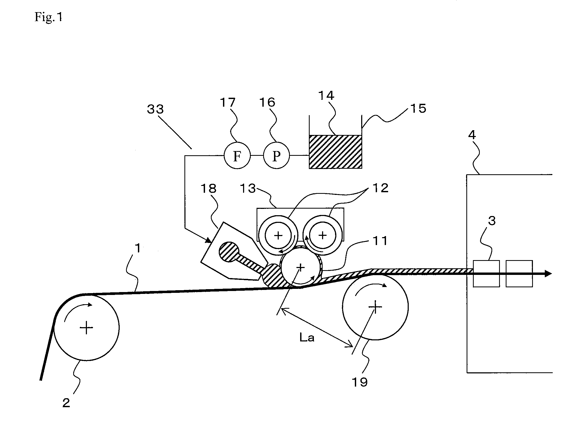
[0086]A biaxially stretched film, in which the cured film of the coating liquid 14 was formed on one surface, was obtained as in Example 1 except that the distance La between the axial centers of the coating rod 11 and the guide roll 19 in Example 1 was set to 1,200 mm, in other words, set to be larger than ½ of the width W of the resin film 1. In this case, the liquid pool was not adequately formed immediately before the portions of the coating rod 11 and the resin film 1 contacting each other, and was discontinuous in the width direction. Further, a large number of coating streaks were detected on the coating surface.

[0087]When the discharge amount of the pump 16 was increased to 770 g / min, the liquid pool was adequately formed, and the coating streaks were no longer detected. The coating width immediately after the smoothening by the coating rod 11 was 1,400±20 mm, and the variation of the coating width stayed in an allowable range in view of the process stability. The thickness ...
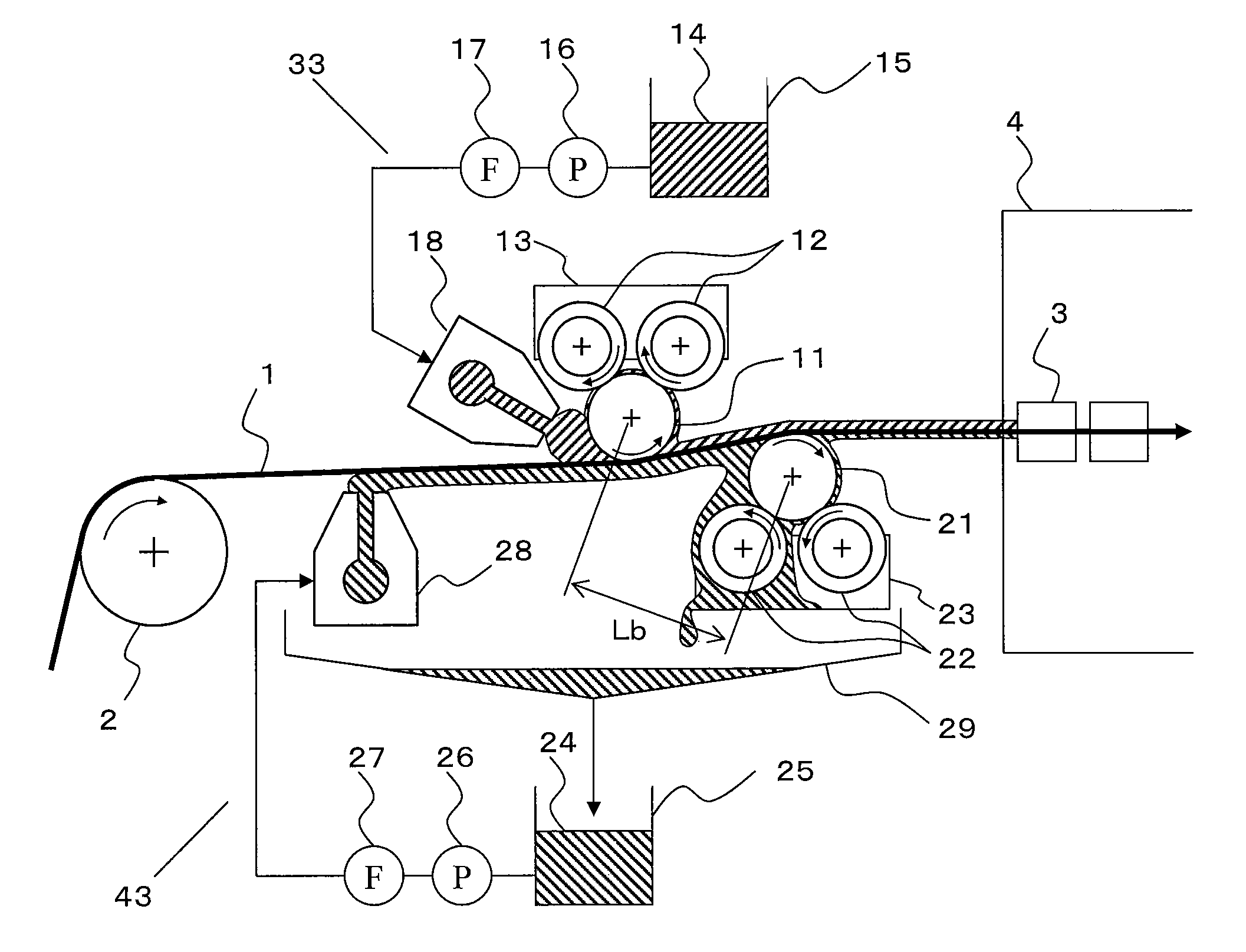
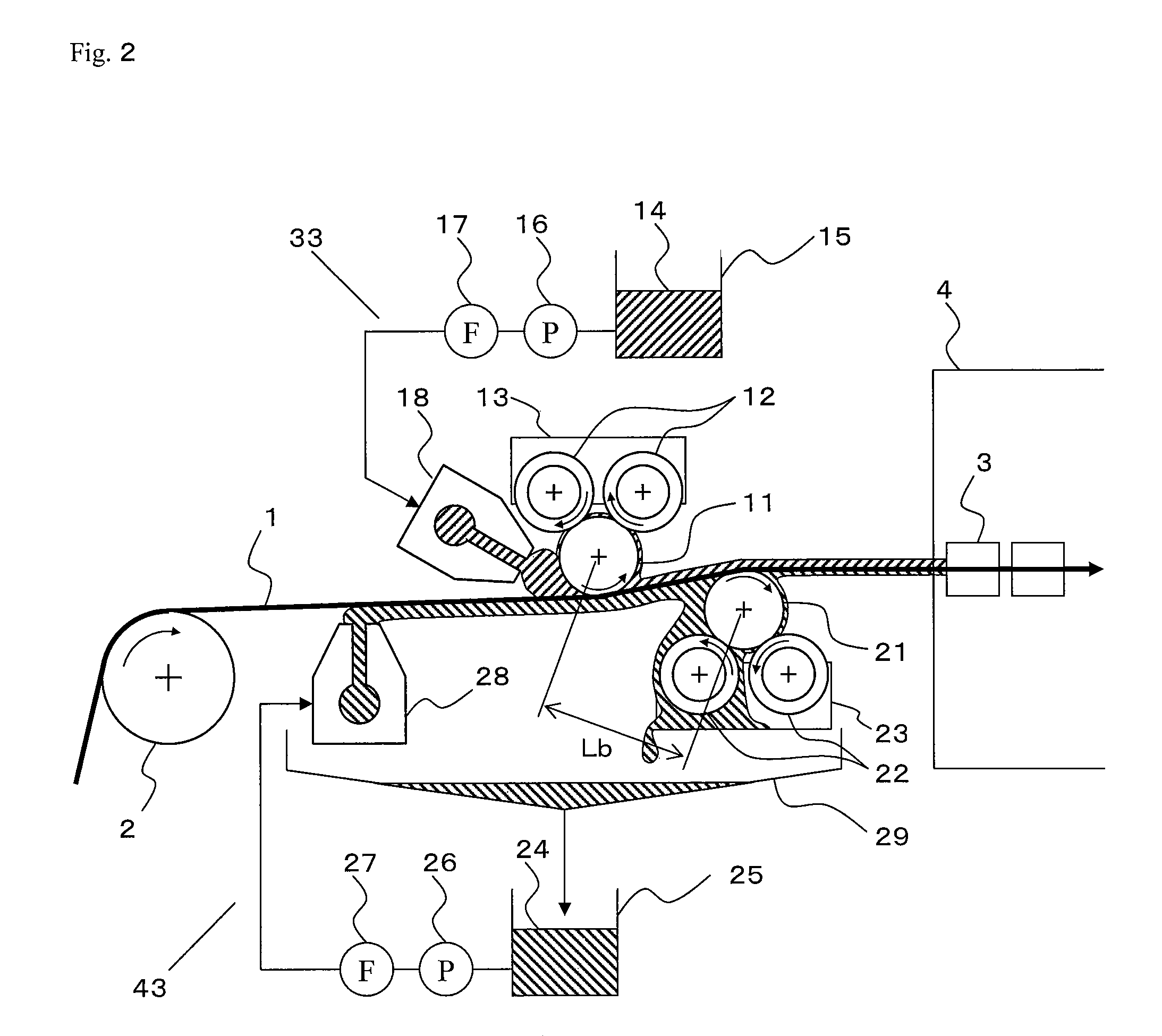
example 3

[0088]The coating liquid 14 was applied to both of the upper surface and the lower surface of the resin film 1 by the coating apparatus shown in FIG. 12. The guide roll 19 in Example 1 was not used, and the lower surface of the resin film 1 was supported by the coating rod 21 instead. A wire rod where a wire made of the material SUS304 and having the diameter of 0.1 mm was wound around a round bar made of the material SUS304, diameter of D2=19 mm, and width of 1,900 mm (manufactured by Kano Shoji Co., Ltd.) so that a groove was formed was used as the second coating rod 21. The distance Lb between the axial centers of the coating rod H and the second rod 21 was set to 100 mm. In the roller 22, thermoplastic polyurethane elastomer having the thickness of 2.5 mm and the degree of hardness of 90 A was bonded to a surface of an aluminum pipe member having the diameter of 17 mm and the width of 14 mm. In the support member 23, two rollers 22 were horizontally disposed with the distance be...


PUM

PropertyMeasurementUnit
viscosityaaaaaaaaaa
viscosityaaaaaaaaaa
thicknessaaaaaaaaaa

Abstract

A first coating rod placed on an upper-surface side of a resin film is pressed onto the resin film in a state where the first coating rod is circumscribed and supported by support members each comprising a pair of rollers and spaced with intervals therebetween in a length direction of the first coating rod so that the first coating rod is rotated in a forward direction at a speed substantially equal to that of the resin film, and a lower surface of the resin film is supported by a guide roll or a second coating rod placed on a downstream side of the first coating rod and an upstream side of a tenter so that the coating liquid continuously measured and supplied to an upper surface of the resin film is smoothened by the first coating rod.

Description

[0001]This is a U.S. National Phase application of application number PCT / JP2007 / 066967, filed Aug. 31, 2007 (which is incorporated herein by reference in its entirety), which claims priority benefit of JP 2006-243956 (filed Sep. 8, 2006).FIELD OF THE INVENTION[0002]The present invention relates to a coating method and a coating apparatus.BACKGROUND OF THE INVENTION[0003]A resin film, for example, a biaxially stretched polyester film, has been widely used as a base film of optical members such as touch panel, liquid crystal display and plasma display. An example of the optical members in which the resin film is used is a hard coat film attached to a front surface of the display. The hard coat film is used such that hard coat films having scratch-resistant, wear-resistant properties, and the like are multilayered on one surface of the resin film. The hard coat films having such properties are constituted by, for example, acrylic resin, urethane resin, melamine resin, epoxy resin, or ...

Claims


Application Information

Patent Timeline
Patent Type & Authority Patents(United States)
IPC IPC(8): B05D3/12
CPCB05C11/025B05D1/26B05D1/40B05D7/04B05C5/0254B05C9/04B05C11/1039B05D2252/10B05D2201/00B05D2252/02B05D1/28B05C1/12
Inventor INOUE, HIROYUKINAGAI, HIROSHITAKASHIMA, NAOHIRO
Owner TORAY IND INC
Why Eureka
Try Eureka