Rotary can opener

a can opener and rotary technology, applied in the field of can opener mechanisms, can solve the problems of long-term changes in the ability of the driven gear to reverse, the “clicking” mechanism operating through continued wear and distracting noise, and the two methods can greatly suffer, so as to achieve smooth operation, less cost, and great freedom.

Active Publication Date: 2013-09-24
DAKA RESEARCH INC
View PDF13 Cites 9 Cited by
  • Summary
  • Abstract
  • Description
  • Claims
  • Application Information

AI Technical Summary

Benefits of technology

[0010]A mechanism is provided for use in an opener for a can, that provides a pair of missing teeth operating endpoints at opposite ends of its opener cycle, along with an eccentrically operating idler gear and cutter gear urging mechanism that produces an easy to operate, extremely quiet, efficient can engagement an opening mechanism. The opener is actuated to a closed and operating position by turning the main drive in a first direction and then actuated to an open and disengaged position by simple reversal caused by turning the main drive in a second direction opposite from the first direction. This eliminates jamming or a “hard stop” that is seen in many openers, while simultaneously eliminating the need for a locking lever or other holding or freeing mechanism.
[0013]The two ended, non-jamming or stopped mechanism allows greater freedom and advantage in both manual and electrically powered can openers. Both electrically and manually driven openers benefit from less expensive parts that would be needed to oppose the stop forces in non-double ended freewheeling operation. For manual can openers the smoother operation makes manual opening much easier, enabling the user to use one hand to steady the well secured can, preferably on a surface, and easily use the other hand to turn an extended crank. The use of lesser cranking force enables the user to better stable the can level as it turns on a surface. The reversal of the crank over only a few turns causes disengagement that is not a surprise spilling disengagement for the user. The pivoting crank handle can be stored with respect to the housing and thus take up minimal space, and in most cases less space than a conventional butterfly can opener. Further, the sharp potentially pinching metal structure relationship found in butterfly can openers is eliminated.

Problems solved by technology

However both of these methods can greatly suffer.
First, any “clicking” mechanism operates through continued wear and distracting noise.
Second, the use of friction among gears in a highly lubricated environment can result in long terms changes in the ability of the driven gear to reverse.
A further undesired by-product of this method of operation is the necessity to grasp the opener with one hand, periodically operate the opener with the other hand, while putting some downward pressure on the can with both hands in order to stabilize the food contents during the opening activity.
A user would not normally think of supporting the can to be opened with the hand supporting the bulk of the opener as the motion would be too much of a jerking motion that would cause a mess.
This is because the manual force necessary to open the can is significant, as well as periodically occurring.
In essence one of the stronger failure modes of the Rosendahl devices occurs at the non-working end of its operational range.
However, the single, blind ended cycle of opening would have caused Rosendahl to have included more complex stopping sensors to insure that any motorized force would not challenge the return to the non-operating position.
Any motorization of this type of end point can set the mechanics of motorization against the mechanics of operation and create destruction of both.
Put another way, the simple provision of the mechanism of Rosendahl into a heavy motorized housing would either have created a significant cost in sensors, electronics to precisely control the cycle, or might have ended with the motorization gearing and the operational gearing destructively fighting with each other.

Method used


Image

  • Rotary can opener
  • Rotary can opener
  • Rotary can opener

Examples


Embodiment Construction

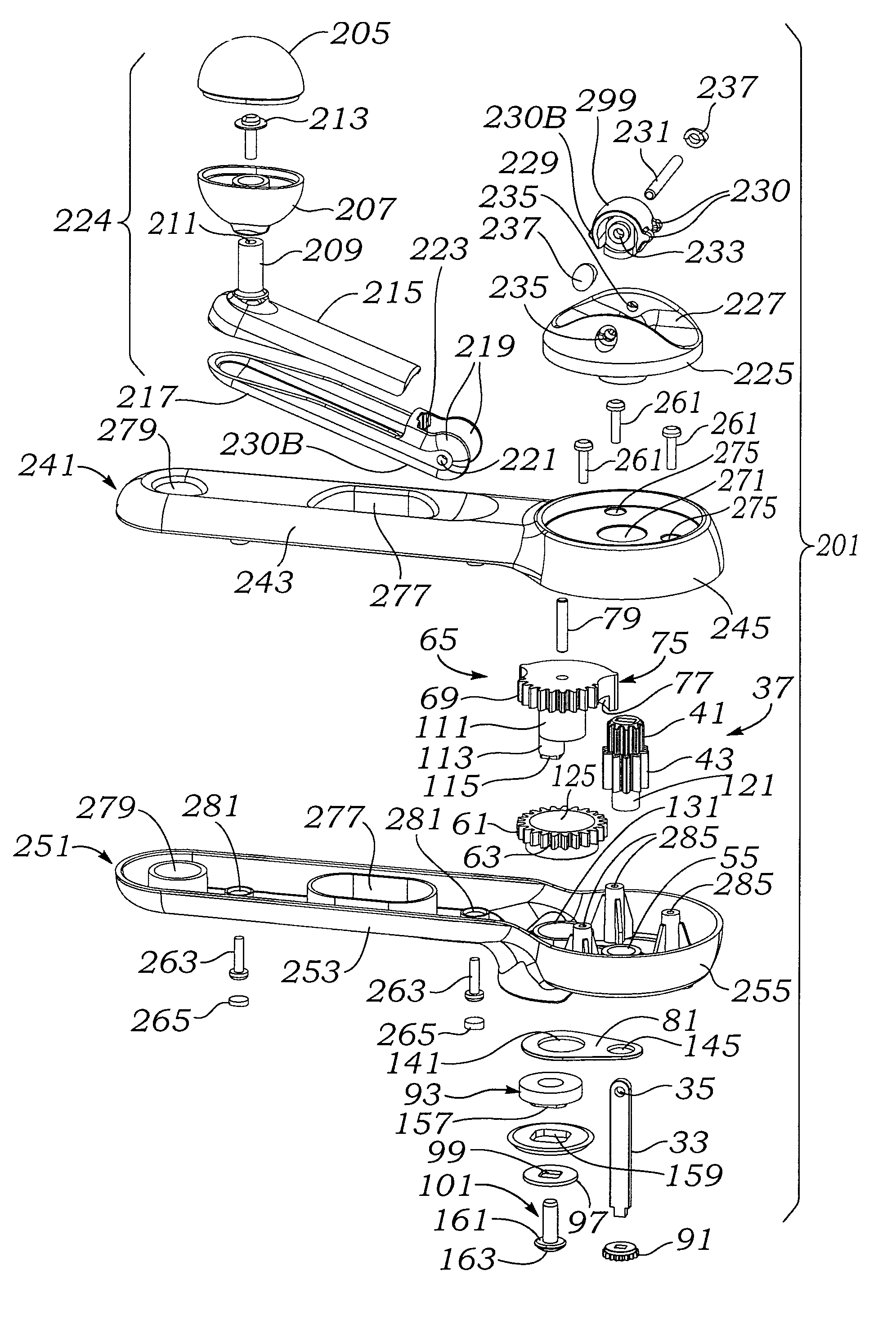
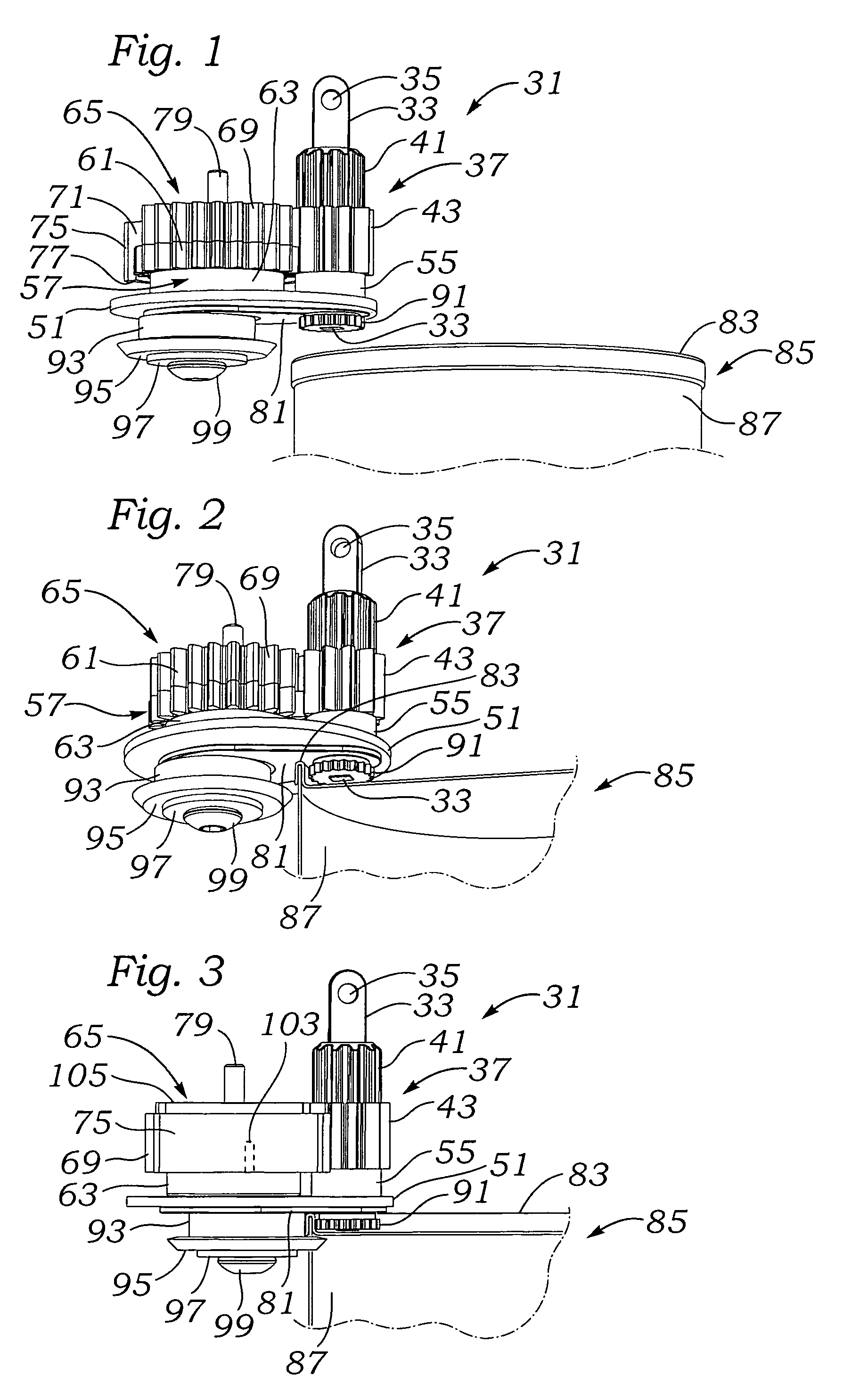
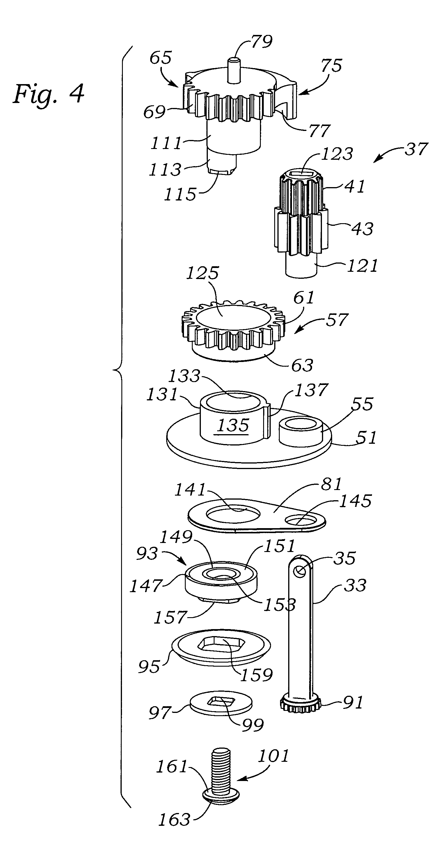
[0032]Referring to FIG. 1, a spatial perspective of the mechanism of the invention hereinafter referred to as rotary can opener mechanism 31 is seen as an operating assembly and without the surrounding housing details. Beginning at the top of the assembly, a drive shaft 33 is seen as having an engagement aperture 35. Drive shaft 33, for strength may preferably be made of metal. Drive shaft 33 is shown extending through an axial drive gear set 37 having an upper engagement gear 41 and a lower drive gear 43.

[0033]A number of structures that are preferably integral to a support housing are illustrated in a position isolated from the remainder of the support housing. A housing section 51 represents the base floor of a lower housing section (not shown) that would provide support for all of the connected components seen at the upper left of FIG. 1. At the right side of the housing section 51 a drive gear boss 55 is shown for rotatably supporting the drive gear 43 at a proper elevation.

[00...


PUM


Abstract

An easy to operate, extremely quiet, efficient can engagement and opening mechanism is provided for use in an opener for a can, and that provides a pair of missing teeth operating endpoints at opposite ends of its opener cycle, along with an eccentrically operating idler gear and cutter gear urging mechanism that produces a non-jamming foolproof mechanism that can be urged forward to a closed and operating position or reversed to a disengagement and non-operating position.

Description

BACKGROUND OF THE INVENTION[0001]1. Field of the Invention[0002]The present invention relates to a mechanism for use in a can opener that uses a quiet reversal mechanism that may be provided with a manual or automated drive mechanisms.[0003]2. Related Background Art[0004]U.S. Pat. No. 4,365,417 issued to Rosendahl on Dec. 28, 1982 and entitled “TIN OPENER” describes a can opener that uses a missing teeth structure at one end of travel of a cutter gear. The open position of the cutter lies at the end of a number of teeth of the cutter movement gear. In essence, a user turns a butterfly shaped actuator from a first, resting stopped position and in a direction of engagement that causes the cutter blade to move toward and engage the body of a can. At the point in which the cutter and the can, urged by a drive wheel, are closest, the drive gear encounters a “missing teeth” section of the cutter gear so that the drive gear can continue to turn the drive wheel and without having the cutter...

Claims


Application Information

Patent Timeline
Patent Type & Authority Patents(United States)
IPC IPC(8): B67B7/70
CPCB67B7/385B67B7/34B67B7/30B67B7/32
Inventor MAH, PAT Y.KALOGROULIS, ALEXANDER JOSHEFTUNG, KWONG KEUNGNG, MICHAEL
Owner DAKA RESEARCH INC
Why Eureka
Try Eureka