Blade drive device
a blade drive and blade technology, applied in the direction of shutters, dynamo-electric machines, magnetic circuit shapes/forms/construction, etc., can solve the problems of large size of high-power actuators and increase the size of blade drive devices, so as to reduce the size and improve the shatter speed
- Summary
- Abstract
- Description
- Claims
- Application Information
AI Technical Summary
Benefits of technology
Problems solved by technology
Method used
Image

Examples
first embodiment
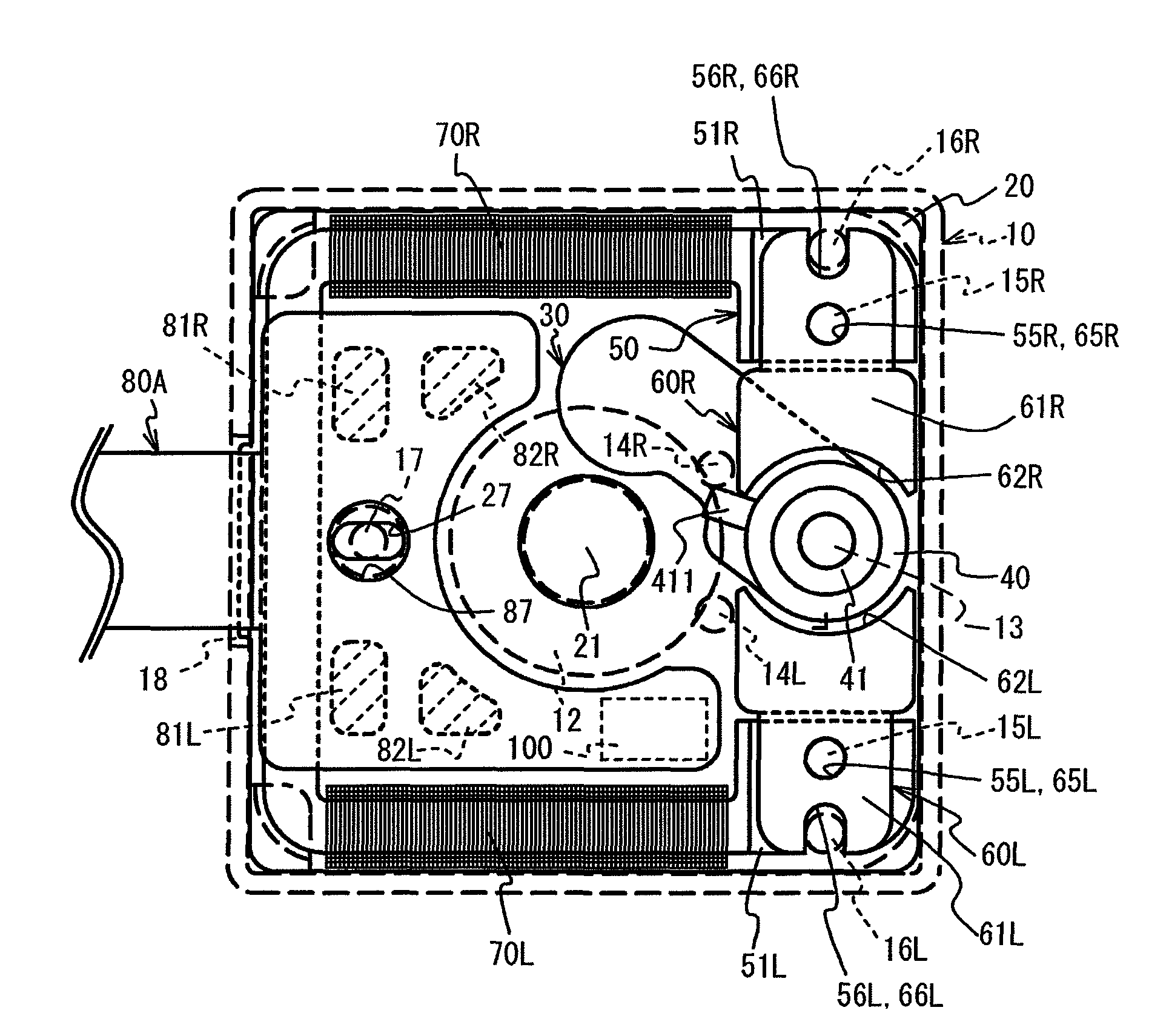
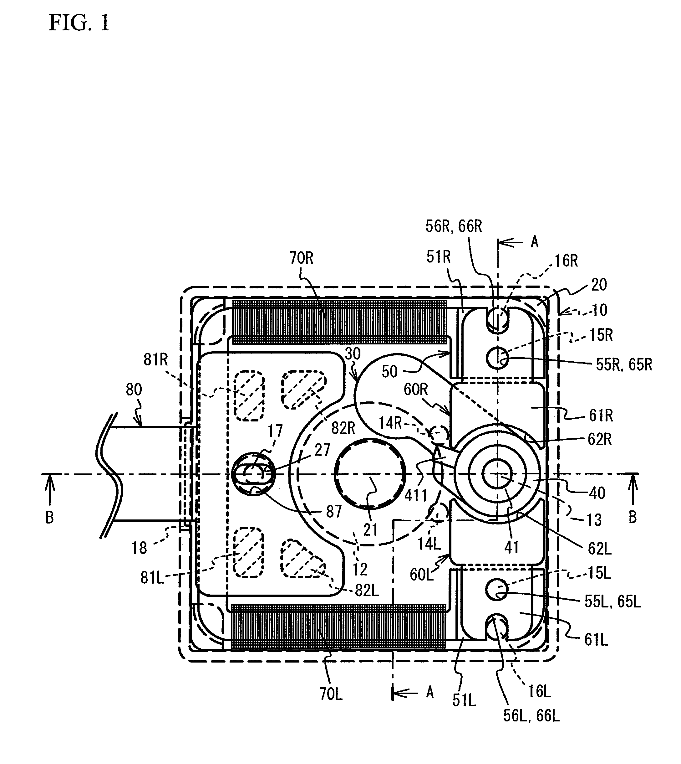
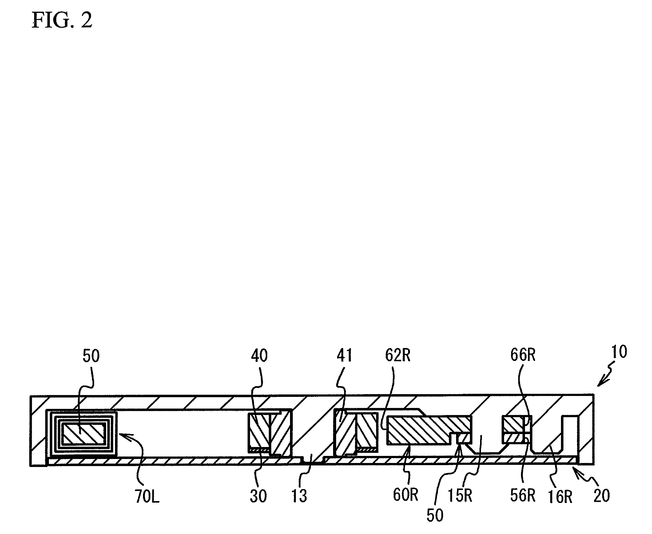
[0023]FIG. 1 is a front view of a configuration of a blade drive device according to a first embodiment. FIG. 2 is a cross-sectional view taken along a line A-A in FIG. 1. FIG. 3 is a cross-sectional view taken along a line B-B in FIG. 1. FIG. 4 is a rear view of a blade drive device according to the first embodiment. The blade drive device according to the first embodiment includes: an upper case 10; a lower case 20; a blade 30; a rotor 40; iron pieces 50, 60L, and 60R; coils 70L and 70R; and a flexible printed circuit board 80.
[0024]The upper and lower cases 10 and 20 serve as a chassis that houses the blade 30, the rotor 40, the iron pieces 50, 60L, and 60R, and a part of the flexible printed circuit board 80, as illustrated in FIGS. 2 and 3. The upper and lower cases 10 and 20 are made of a synthetic resin. The upper case 10 is thicker than the lower case 20. The blade drive device according to the first embodiment is attachable to an image pickup apparatus or a lens drive appar...
second embodiment
[0053]Next, a description will be given of a blade drive device according to a second embodiment with reference to the drawings. Additionally, in the blade drive device according to the second embodiment, components that are similar to those of the first embodiment will be denoted by the same reference numerals as used in connection with the first embodiment, and a detailed description of such components will be omitted.
[0054]FIG. 8 is a front view of a configuration of the blade drive device according to the second embodiment. FIG. 9 is a front view of the blade drive device according to the second embodiment with a flexible print substrate being omitted. FIG. 10 is a cross-sectional view taken along a line C-C in FIG. 8.
[0055]As illustrated in FIGS. 8 and 9, a rotor 40a is located at a corner portion of upper and lower cases 10a and 20a each has a rectangular shape as seen in the optical axis direction. Additionally, iron pieces 50La and 50Ra serve as a stator and each has an iden...
PUM
 Abstract
Description
Claims
Application Information
 - R&D
- Intellectual Property
- Life Sciences
- Materials
- Tech Scout
- Unparalleled Data Quality
- Higher Quality Content
- 60% Fewer Hallucinations
Browse by: Latest US Patents, China's latest patents, Technical Efficacy Thesaurus, Application Domain, Technology Topic, Popular Technical Reports.
© 2025 PatSnap. All rights reserved.Legal|Privacy policy|Modern Slavery Act Transparency Statement|Sitemap|About US| Contact US: help@patsnap.com