Containment system

a technology of containment and container, applied in the direction of transportation and packaging, rigid containers, packaging, etc., can solve the problems of heavy weight and difficulty in assembling members, and achieve the effect of significantly reducing the fabrication cost of members

Active Publication Date: 2013-09-24
POLYSTAR
View PDF42 Cites 17 Cited by
  • Summary
  • Abstract
  • Description
  • Claims
  • Application Information

AI Technical Summary

Benefits of technology

[0006]In accordance with the invention, a modular containment system is provided with a limited number of easily assembled straight and corner or curved members. The members are formed of a moldable plastic material. Consequently, the fabrication cost of the members is significantly reduced as compared with prior art barrier systems.
[0011]In preferred arrangements, the member is hollow and both side walls extend at the same inclined angle relative to the base. The rigidity of the members is increased by forming separate reinforcing ribs in the side wall. In the illustrated embodiment, ribs are provided in each of the side walls and extend along major area portions of the side walls.
[0012]Preferably, the ribs extend in intersecting angular directions so as to increase rigidity and resist buckling in corresponding directions. Thus, the ribs may be generally disposed in a vertical direction in one side wall and a horizontal direction in the other side wall so as to resist flexure of the member in both vertical and horizontal directions.
[0013]The ribs have a height equal to about one-half of the overall wall thickness of the member as defined by the spaced side walls. Accordingly, the interior surfaces of the opposed side walls are closely spaced and substantially abut at locations between the ribs. The close spacing of the interior surfaces of the side walls results in engagement upon loading and flexure of the member whereby the side walls tend to reinforce each other.

Problems solved by technology

Although portable, the strut and corner members are formed of glass fiber reinforced plastics requiring labor intensive and costly construction and results in a rather heavy and difficult to assemble members.
Further, the strut and corner members are generally of trapezoidal cross-section and do not resist surge flows as may occur with a major leak or rupture of the primary container.
As to be expected, the prior art barrier systems are heavy and raise transportation considerations, especially at remote installation cites and / or tight-fitting tortuous industrial installations wherein the delivery path may be tortuous.

Method used


Image

  • Containment system
  • Containment system
  • Containment system

Examples


Embodiment Construction

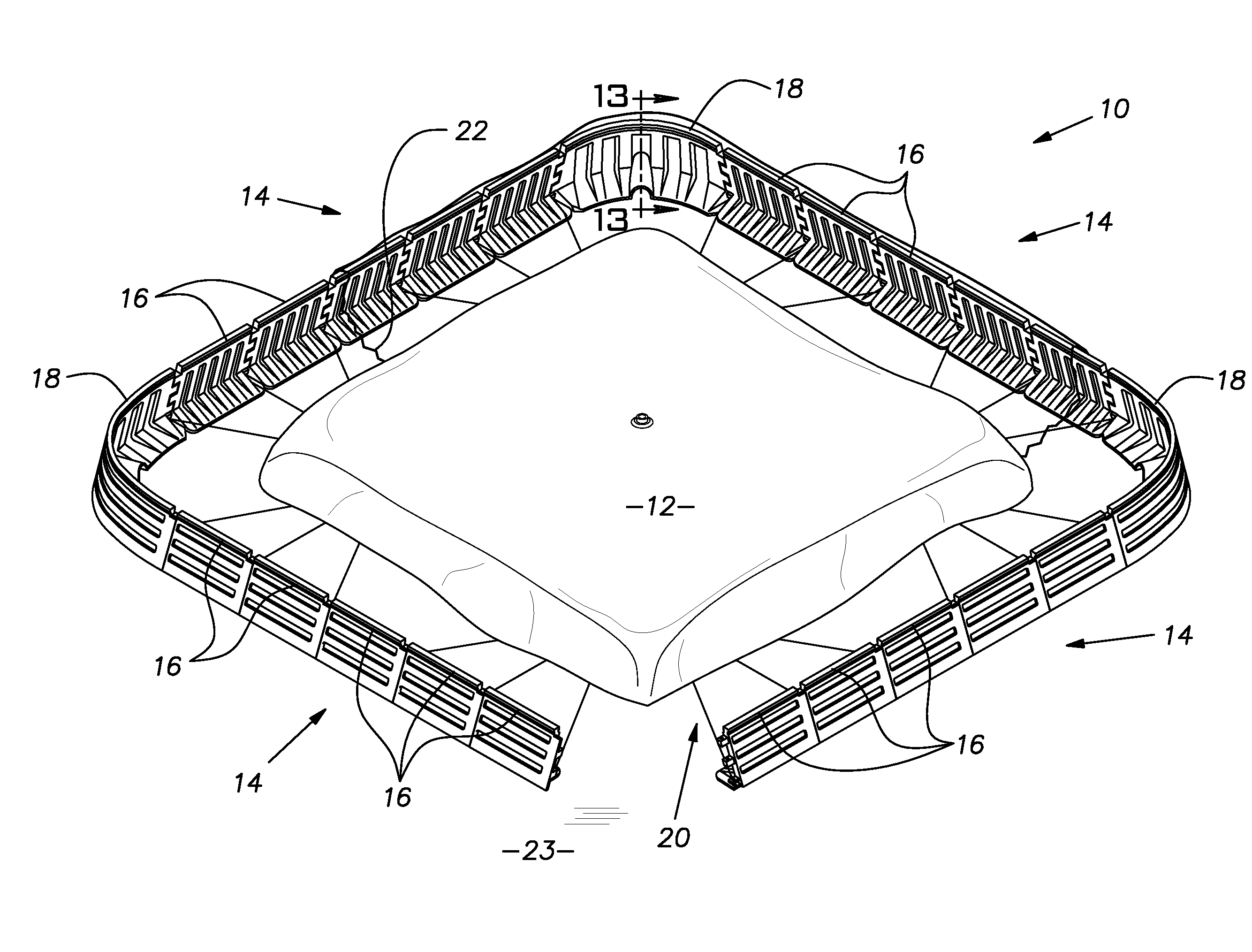
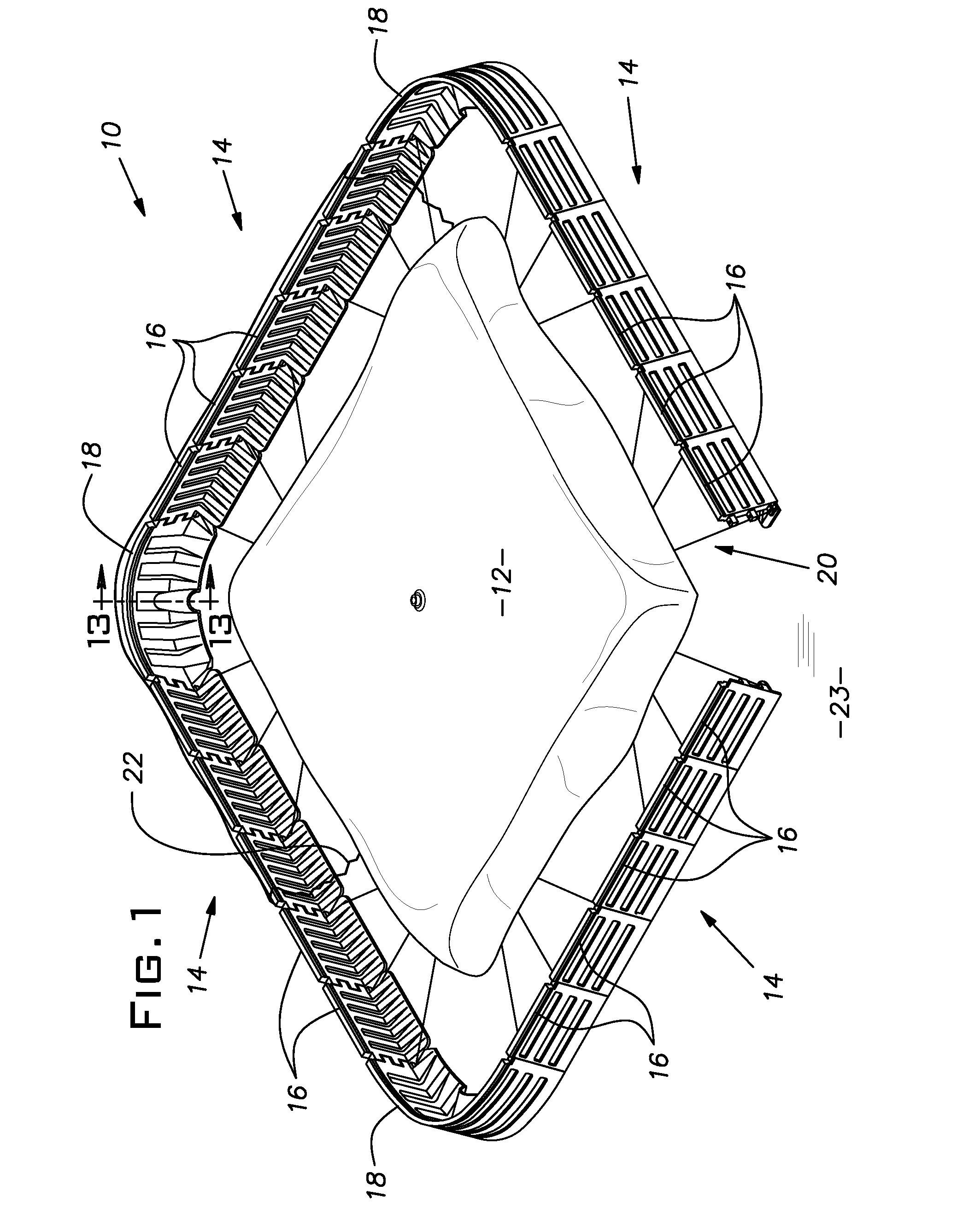
[0028]A closed barrier or dike assembly 10 surrounding a primary container 12 is shown in FIG. 1. The primary container 12 is a flexible bladder construction that may contain a fuel to be isolated from the environment in case of container failure or as required by environmental regulations. The primary container may comprise a storage tank (not shown) for industrial liquid supplies such as lubricants, solvents, reactants or any other liquid requiring secondary containment.

[0029]The dike assembly 10 has a generally rectangular configuration with rounded corners provided by opposed dike walls 14 formed by interlocked straight members 16 extending between and interlocked with corner members 18. A cable web 20 is provided for securing the members 16 and 18 together as further explained below.

[0030]For purposes of liquid containment, a liquid impermeable barrier film or liner 22 is disposed between the primary container 12 and the web 20, along the substratum 23 and over the dike walls 1...


PUM


Abstract

A modular dike or barrier assembly includes straight and curved members that may be interconnected to form a barrier or dike wall surrounding a primary container. The members are hollow and include opposed side walls having integrally formed reinforcing ribs. The side walls extend at an acute angle relative to the base of the barrier to contain and redirect a surge flow directed toward the dike or barrier assembly. The interior surfaces of the side walls are closely spaced at locations spaced from the ribs and tend to abut for added wall reinforcement upon application of wall deflecting loads.

Description

BACKGROUND OF THE INVENTION[0001]The present invention relates generally to secondary containment systems typically used in connection with hazardous materials or other materials to be isolated from the environment. More particularly, a deployable modular containment system includes straight and curved members that may be interconnected to form a closed barrier or a dike wall surrounding a primary container or otherwise isolating the selected material. The barrier or dike system may be used to restrict liquid flows of other origins such as a flood or other disaster resulting in an unregulated or diverted flow of liquid.[0002]It is known to use secondary containment systems for reducing, if not eliminating, accidental spill of materials being stored or processed. For example, steel drum storage of hazardous materials may require secondary containment under applicable environmental regulations. Military fuel storage may be provided in a primary container surrounded by a secondary cont...

Claims


Application Information

Patent Timeline
Patent Type & Authority Patents(United States)
IPC IPC(8): E02B7/08
CPCB65D90/24
Inventor MARSHALL, AARON D.
Owner POLYSTAR
Why Eureka
Try Eureka