Method and device for producing images of heating tines near a tissue part

a technology for heating tines and tissue parts, applied in medical science, surgical instruments for cooling, surgery, etc., can solve the problems of difficult visualization of heating tines, incomplete treatment of desired tumor-region ablation, and often not uniform deployment of heating tines

Active Publication Date: 2013-09-24
KONINK PHILIPS ELECTRONICS NV
View PDF5 Cites 16 Cited by
  • Summary
  • Abstract
  • Description
  • Claims
  • Application Information

AI Technical Summary

Benefits of technology

[0062]a means for combining the acquired ultrasound image data with position data representative of the deduced relative positions to compel said screen to display real time images of the area with thermal strain information showing the relative positions of the heating tines to the chosen tissue part, in order to allow the operator to determine if the heating tines are positioned at the desired areas and to adjust the position of at least one of the heating tines.

Problems solved by technology

But, due to inhomogeneities in tissues and vessels (including in tissue and vessel stiffness), actual heating tine deployment is often not uniformly accomplished, which produces cold spots that do not allow local ablations, and / or induces flattening of heating tines, which produces a more pyramidal treatment volume instead of a desired spherical or toroidal shaped volume.
But the visualization of the heating tines appears to be difficult, notably with a conventional B-mode ultrasound technique, due to the size of the heating tines and the brightness of the surrounding tissues (a portion of a heating tine or of a subset of heating tines can be visualized if it is well oriented relative to the ultrasound beam).
But, when the deployment is partly incorrect, ablation errors may occur, resulting in smaller-than-desired ablation areas and thus incomplete treatment of desired tumor-region ablation.

Method used


Image

  • Method and device for producing images of heating tines near a tissue part
  • Method and device for producing images of heating tines near a tissue part
  • Method and device for producing images of heating tines near a tissue part

Examples


Embodiment Construction

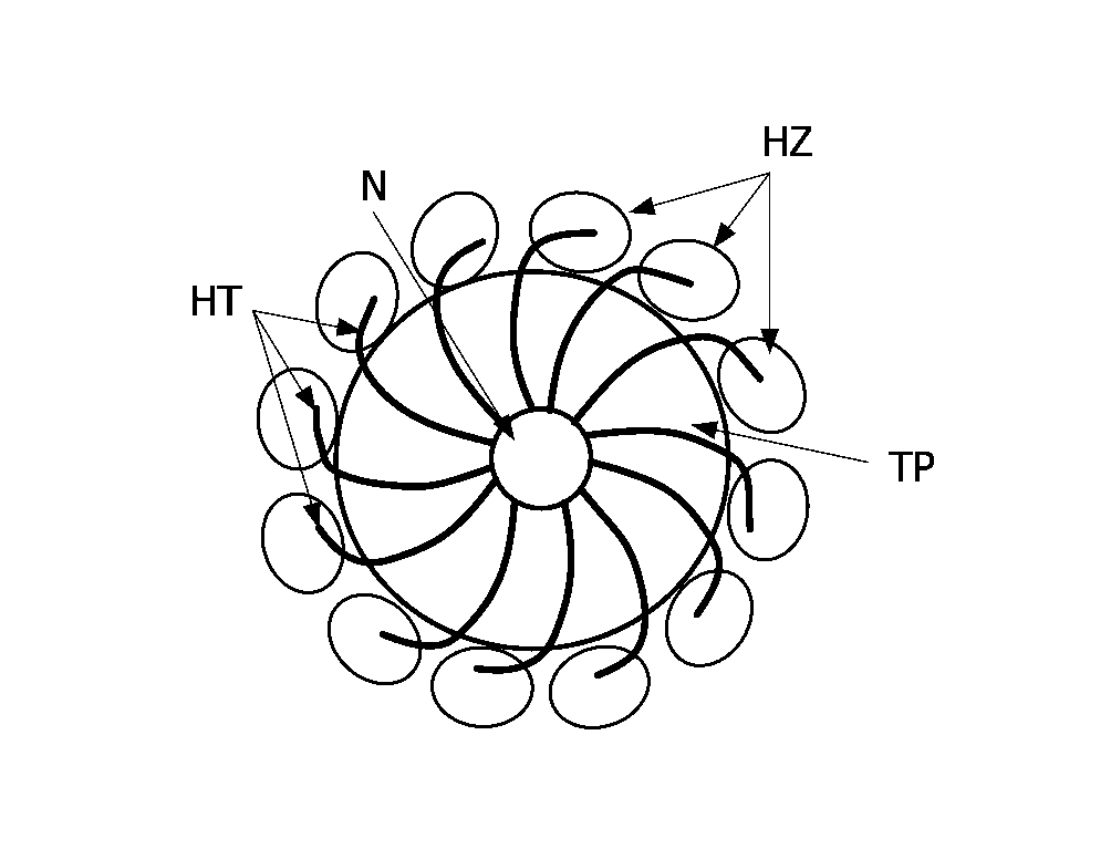
[0078]As mentioned in the introductory part, the invention aims at producing images of an area showing the relative positions of heating tines coupled to a needle relative to a chosen tissue part of a body, for instance to improve the positioning of these heating tines, and hence to improve the efficiency of an ablation technique and to reduce the occurrence of errors.

[0079]For this purpose, the invention notably proposes an image production device and an image production method.

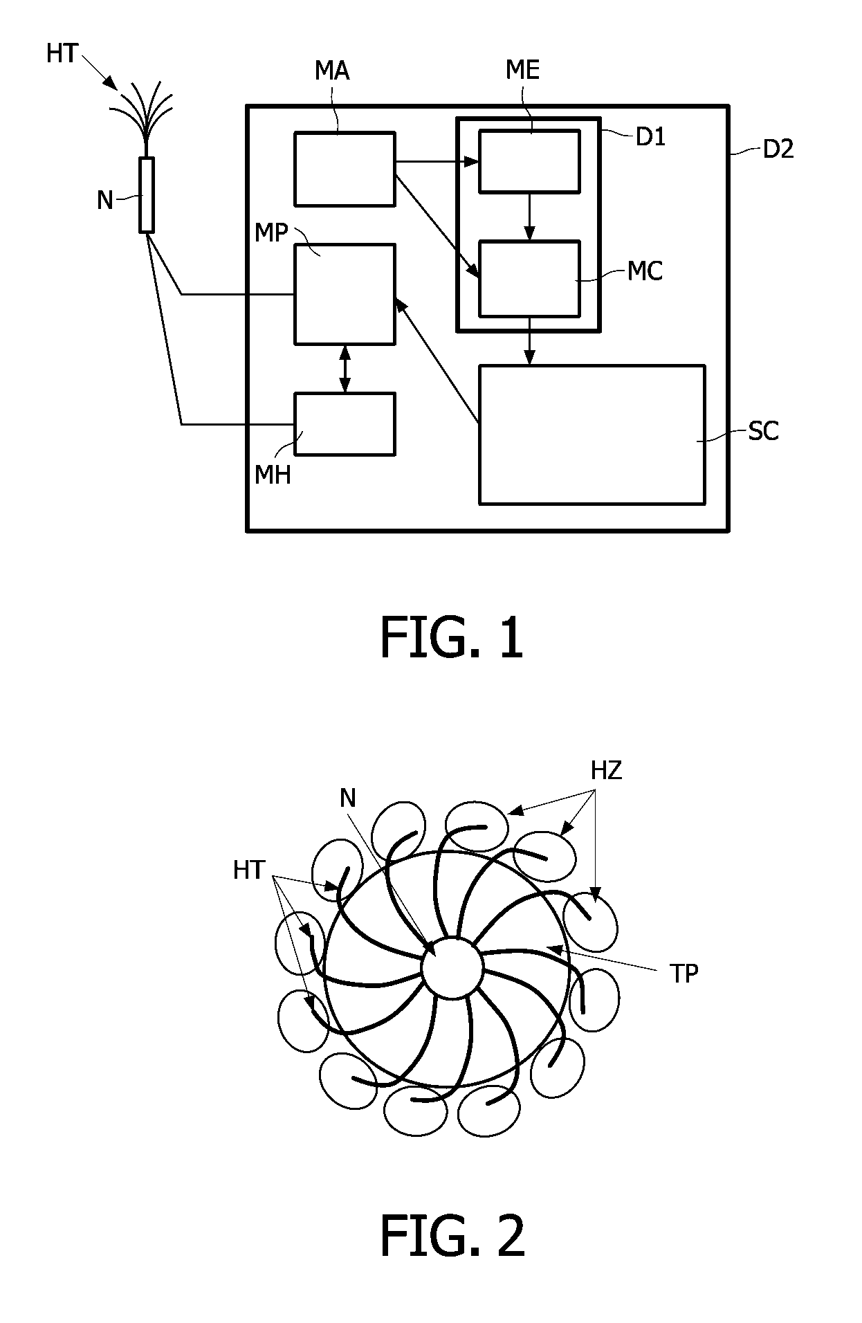
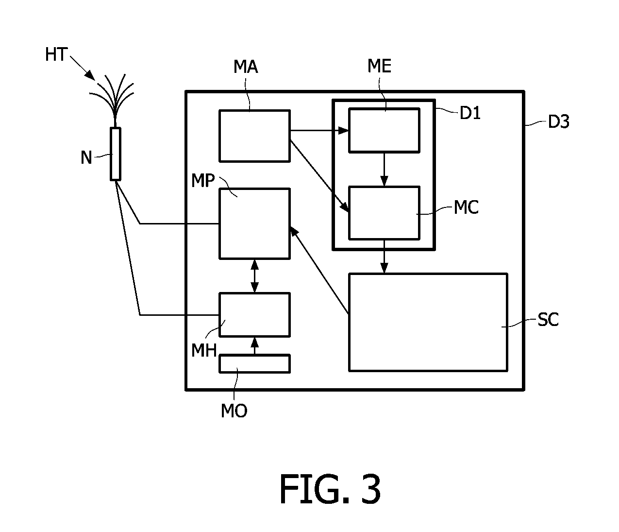
[0080]Reference is initially made to FIGS. 1 and 2 to present the image production method and an example of embodiment of an image production device D1 according to the invention. In the non limiting illustrated example the image production device D1 is part of an example of embodiment of a positioning device D2 according to the invention. But this is not mandatory.

[0081]A positioning device D2 comprises at least an array of heating tines HT coupled to a needle N, an image acquisition means MA, a screen SC, ...


PUM


Abstract

A device (D1) is intended for producing images of heating tines (HT) coupled to a needle (N) positioned near a chosen tissue part of tissues located in an area of a body. This device (D1) comprises i) a means (ME) for estimating tissue thermal strains, induced by means of the heating tines (HT) into the tissue surrounding the chosen tissue part, from received ultrasound image data, and for deducing relative positions of these heating tines (HT) to the chosen tissue part from the estimated tissue thermal strains, and ii) a means (MC) for combining the received ultrasound image data with position data representative of the deduced relative positions to produce images of the area with thermal strain information showing the relative positions of the heating tines (HT) to the chosen tissue part.

Description

FIELD OF THE INVENTION[0001]The present invention relates to the production of images of an array of heating tines coupled to a needle around a chosen tissue part of tissues located in an area of a body, and to the assisted positioning of this array, notably for ablating this chosen tissue part.[0002]One means here by “ablating” a process consisting in heating a tissue to induce cell destruction (or death). The “dead tissue” is next removed by the body for instance through its lymphatic system and then replaced by scar tissue.BACKGROUND OF THE INVENTION[0003]As it is known by the man skilled in the art, ablation of a chosen tissue part, such as a tumor (for instance a liver tumor (both primary and metastases) or a renal tumor or else uterine fibroids), can now be done in a minimally invasive way by an operator (generally a surgeon, a radiologist, or an interventional radiologist) by means of a remotely controllable needle coupled to an array of heating tines which can be deployed fr...

Claims


Application Information

Patent Timeline
Patent Type & Authority Patents(United States)
IPC IPC(8): A61B8/00
CPCA61B8/0833A61B8/0841A61B8/4416A61B8/485A61B18/1477A61B18/02A61B2017/00084A61B2018/143A61B2018/1432A61B2019/5276A61B2090/378
Inventor BRUCE, MATTGAUTHIER, THOMASXIEA, HUAFERNANDEZ, ANNA T.
Owner KONINK PHILIPS ELECTRONICS NV
Why Eureka
Try Eureka