Portable ultrasound with touch screen interface

a touch screen interface and ultrasound technology, applied in the field of ultrasound systems, can solve the problems of inability to effectively display ultrasound images, difficult process, and need cleaning of the overlay,

Inactive Publication Date: 2008-05-22
NORTH AMERICAN MEDICAL CORPORTAION
View PDF4 Cites 137 Cited by
  • Summary
  • Abstract
  • Description
  • Claims
  • Application Information

AI Technical Summary

Benefits of technology

[0011]The disadvantages of the prior art are overcome by the present invention which, in one aspect, is an ultrasound system for imaging an object using data received from an ultrasound transducer. A first touch screen is configured to display ultrasound images and to receive control inputs relating to the images. A second touch screen is configured as a user input device. A processor is coupled to the ultrasound transducer so as to receive data therefrom. The processor is also coupled to the first touch screen and to the second touch screen. The processor is configured to generate ultrasound images based on the data received from the ultrasound transducer. The processor is also configured to cause the first touch screen to display the ultrasound images. The processor is also configured to receive control input data from the first touch screen and the second touch screen.
[0012]In another aspect, the invention is an ultrasound system that includes an ultrasound transducer, a first touch screen, a second touch screen, and a processor. The processor is configured to drive the ultrasound transducer and to receive signals therefrom. The processor is electrically coupled to the first touch screen and to the second touch screen. The processor includes a memory on which is stored a program. The program is configured to: drive the first touch screen so as to display on the first touch screen an ultrasound image corresponding to ultrasound data received from the ultrasound transducer, drive the second touch screen so as to display an image of a control interface that includes at least one specific input field indicative of a control value, receive at least one user input juxtaposed with the specific input field, and modify an operating parameter of the ultrasound system so as to conform to the control value. A battery is electrically coupled to, and configured for providing power to, the ultrasound transducer, the processor, the first touch screen and the second touch screen. A briefcase includes a first half that is hingedly attached to a second half. The first touch screen is mounted in the first half and the second touch screen is mounted in the second half. The processor is mounted in a selected one of the first half and the second half and the battery is mounted in a selected one of the first half and the second half.
[0013]In yet another aspect, the invention is an ultrasound apparatus for allowing a user to perform ultrasound imaging. The ultrasound apparatus includes an ultrasound transducer, a processor and a touch screen. The processor is configured to drive the ultrasound transducer and to receive signals therefrom. The touch screen is coupled to the processor. The touch screen is configured to display ultrasound images and to receive control inputs from the user so that the apparatus employs only the touch screen for both displaying the ultrasound images and for receiving the control inputs.

Problems solved by technology

However, this is a difficult process since the keyboard typically has an uneven surface.
However, this approach still requires cleaning of the overlay, which may be difficult because of its irregular shape.
However, such systems typically also include a traditional keyboard for data input or are too small for the effective display of ultrasound images.
Typical systems that employ keyboards are bulky, which makes performing ultrasound imaging away from a clinic difficult.
This system has a relatively small screen that does not facilitate highly precise real-time diagnostics in many situations.

Method used


Image

  • Portable ultrasound with touch screen interface
  • Portable ultrasound with touch screen interface
  • Portable ultrasound with touch screen interface

Examples


Embodiment Construction

[0020]A preferred embodiment of the invention is now described in detail. Referring to the drawings, like numbers indicate like parts throughout the views. As used in the description herein and throughout the claims, the following terms take the meanings explicitly associated herein, unless the context clearly dictates otherwise: the meaning of “a,”“an,” and “the” includes plural reference, the meaning of “in” includes “in” and “on.”

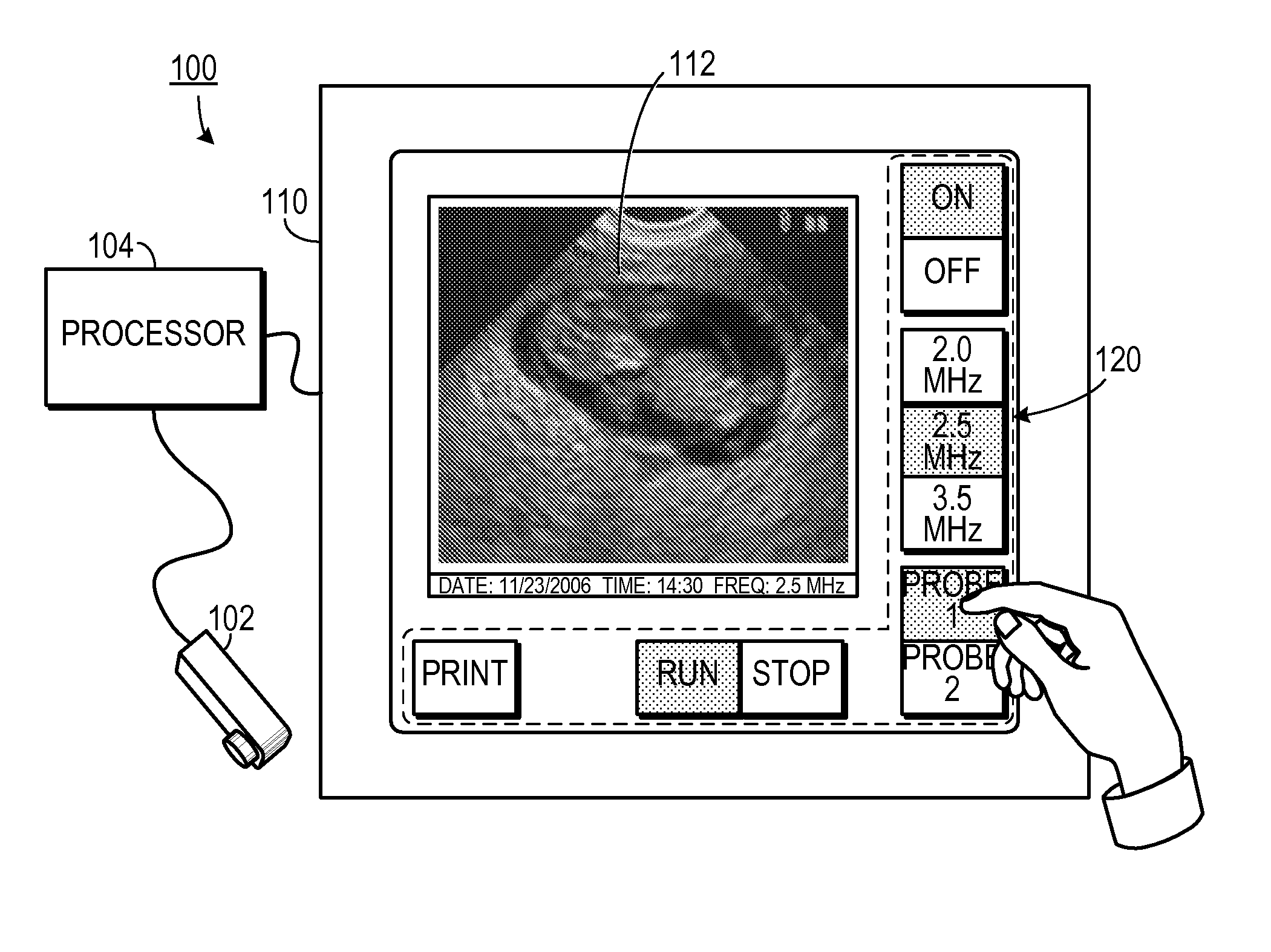
[0021]As shown in FIG. 1, one embodiment of the invention includes an ultrasound system 100 for imaging an object. The system 100 includes an ultrasound transducer 102 that generates an ultrasound imaging signal and that receives a return ultrasound imaging data signal (which could be in the form of analog data, digital data, or a combination thereof).

[0022]A processor 104 drives the ultrasound transducer 102 and receives a data signal therefrom. A touch screen 110 is coupled to the processor 104. The touch screen 110 is configured to display an ultrasou...


PUM


Abstract

An ultrasound system for imaging an object using data received from an ultrasound transducer employs a first touch screen configured to display ultrasound images and to receive control inputs relating to the images. A second touch screen is configured as a user input device. A processor is coupled to the ultrasound transducer so as to receive data therefrom. The processor is also coupled to the first touch screen and to the second touch screen. The processor is configured to generate ultrasound images based on the data received from the ultrasound transducer. The processor is also configured to cause the first touch screen to display the ultrasound images. The processor is also configured to receive control input data from the first touch screen and the second touch screen.

Description

CROSS-REFERENCE TO RELATED APPLICATION[0001]This application claims the benefit of U.S. Provisional Patent Application Ser. No. 60 / 866470, filed 11 / 20 / 2006, the entirety of which is hereby incorporated herein by reference.BACKGROUND OF THE INVENTION[0002]1. Field of the Invention[0003]The present invention relates to ultrasound systems and, more specifically, to a portable ultrasound system.[0004]2. Description of the Prior Art[0005]Ultrasound imaging has long been used by physicians, and other health care professionals, to view images of phenomena within a body. A typical ultrasound imaging system includes a transducer, a keyboard input, a computer and a display screen. The health care professional enters system input to the computer via the keyboard and views images on the display screen.[0006]Typically, gels and other fluids get on the hands of the health care professional using an ultrasound imaging system. These fluids can be transferred to the keyboard. Thus, the keyboard must...

Claims


Application Information

Patent Timeline
Patent Type & Authority Applications(United States)
IPC IPC(8): A61B8/00
CPCA61B8/00A61B8/463A61B8/4427A61B8/467A61B8/465A61B8/461
Inventor BECERRA, CARLOSCHANDLER, WILLIAM K.ZELEKE, ABEBAW
Owner NORTH AMERICAN MEDICAL CORPORTAION
Why Eureka
Try Eureka