Method for mounting a portable device

a portable device and mounting method technology, applied in the direction of machine supports, furniture parts, manufacturing tools, etc., can solve the problems of further limiting so as to limit the usefulness of the clamp

Active Publication Date: 2013-10-01
NAT PRODS
View PDF12 Cites 27 Cited by
  • Summary
  • Abstract
  • Description
  • Claims
  • Application Information

AI Technical Summary

Benefits of technology

[0003]The known spring-driven rotational clamps of the prior art is directed to mounting device holders on external surfaces having a narrow projecting surface, such as flat screen computer monitors and the like having a narrow projecting surface small enough to receive the arms of the around it, which severely limits the usefulness of the clamp. Furthermore, the structure for receiving the camera is limited to the standard ¼ inch-20 threaded connection common to cameras, which further limits the clamp's usefulness.
[0005]Accordingly, based upon applicant's realization, his invention provides for a quick and easy clamping structure that does not require the external mounting surface to be narrow and rigid, as in the prior art. None of this is disclosed, suggested by, or obvious from applicant's prior art or prior art familiar to the applicant.

Problems solved by technology

The known spring-driven rotational clamps of the prior art is directed to mounting device holders on external surfaces having a narrow projecting surface, such as flat screen computer monitors and the like having a narrow projecting surface small enough to receive the arms of the around it, which severely limits the usefulness of the clamp.
Furthermore, the structure for receiving the camera is limited to the standard ¼ inch-20 threaded connection common to cameras, which further limits the clamp's usefulness.

Method used


Image

  • Method for mounting a portable device
  • Method for mounting a portable device
  • Method for mounting a portable device

Examples


Embodiment Construction

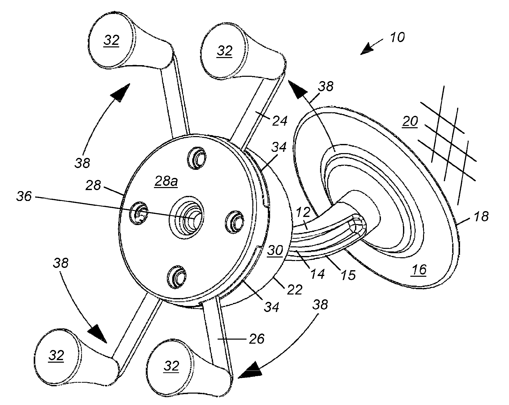
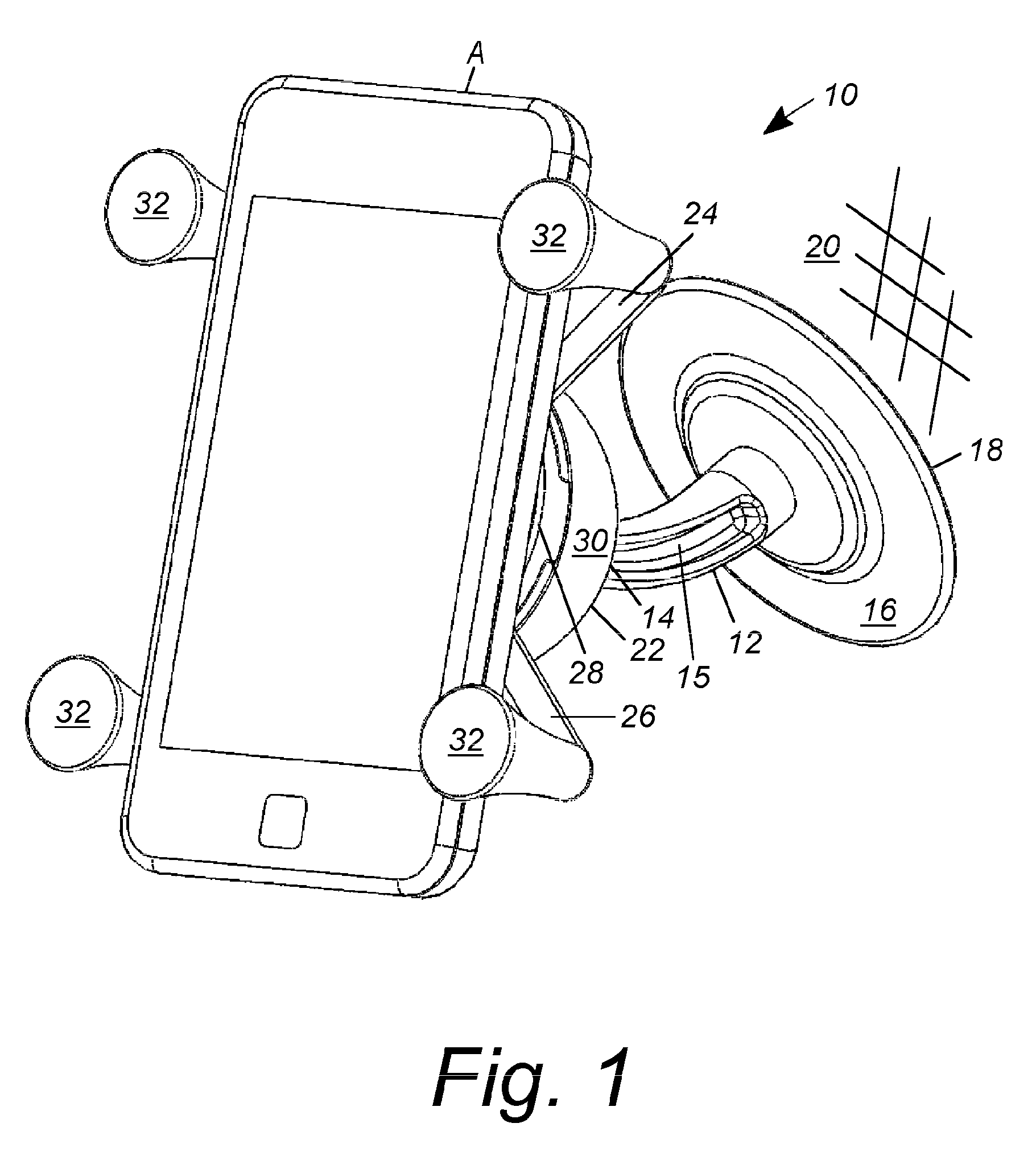
[0020]Although the following discussion is directed toward use of the present invention in conjunction with hand-held portable telephones, those skilled in the art will recognize that the present invention may be utilized to securely mount a wide variety of similar articles at a convenient location. Thus, discussion of the present invention in conjunction with a hand-held portable telephone is by way of example only and not by way of limitation.

[0021]As required, a detailed illustrative embodiment of the present method of clamping a normally hand-held device is disclosed herein. However, techniques, systems and operating structures in accordance with the present method of clamping a normally hand-held device may be embodied in a wide variety of forms and modes, some of which may be quite different from those in the disclosed embodiment. Consequently, the specific structural and functional details disclosed herein are merely representative, yet in that regard, they are deemed to affo...


PUM

PropertyMeasurementUnit
compressive clamping relationshipaaaaaaaaaa
compressive clampingaaaaaaaaaa
resilient urging forceaaaaaaaaaa

Abstract

A method of mounting a hand-held portable telephone or other normally hand-held portable device, wherein the method includes: mounting a body of a portable device holder on a mounting surface external of the portable device holder with a base surface thereof facing substantially away from the mounting surface; rotating opposing arms apart around a central post interior of the body, whereby substantially upright opposing fingers adjacent to ends of the arms are rotated apart; inserting a portable device between the rotated apart opposing fingers; and resiliently urging together the rotated apart opposing arms, whereby opposing fingers are urged into compressive contact with the portable device.

Description

FIELD OF THE INVENTION[0001]The present invention relates generally to clamping methods for mounting portable devices, and in particular to spring-driven quick release clamping methods for portable phones, ipads, and other hand-held portable electronics devices.BACKGROUND OF THE INVENTION[0002]Spring-driven clamps are known for mounting device holders to hold small cameras onto flat screen computer displays for the purpose of web conferencing, the clamp being coupled at the camera's base by a standard ¼ inch-20 threaded connection and operated to grip a suitable external mounting surface of the flat screen computer display. However, such known clamps are limited in their ability to provide a universal mounting solution because the external mounting surface for the clamp is limited to a projection surface, such as the flat screen computer display, that is narrow enough to receive the arms of the around it and rigid enough to stand up under the load. Also, the structure of the clamp f...

Claims


Application Information

Patent Timeline
Patent Type & Authority Patents(United States)
IPC IPC(8): A47G29/08
CPCB60R11/0235B60R11/0241F16M11/041F16M11/14F16M13/00F16M13/022H04M1/04B60R2011/008B60R2011/0056B60R2011/0071B60R2011/0078Y10T29/49826Y10T29/4987
Inventor CARNEVALI, JEFFREY D.
Owner NAT PRODS
Why Eureka
Try Eureka