Lazy susan device with snap fit top and base
- Summary
- Abstract
- Description
- Claims
- Application Information
AI Technical Summary
Benefits of technology
Problems solved by technology
Method used
Image
Examples
Embodiment Construction
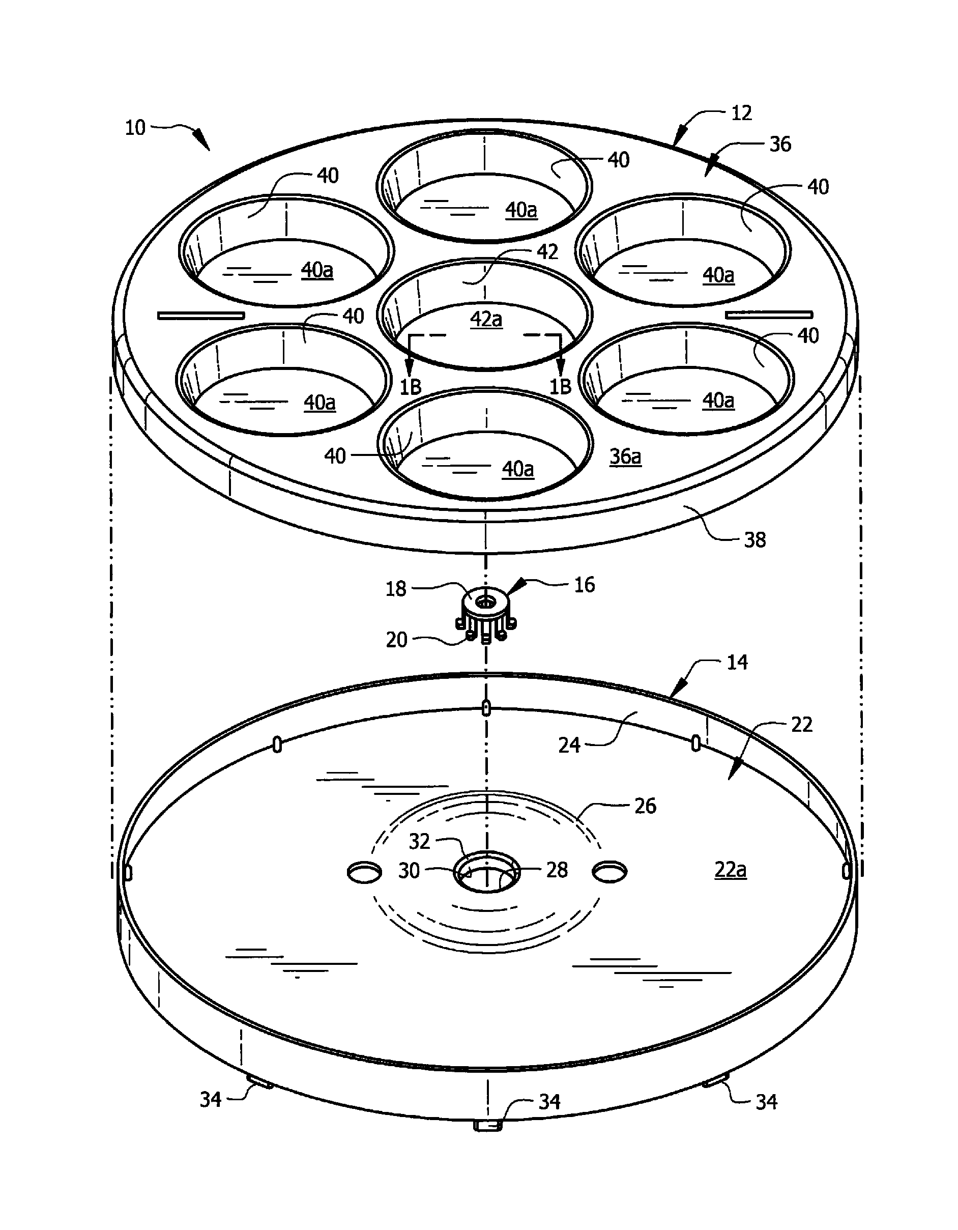
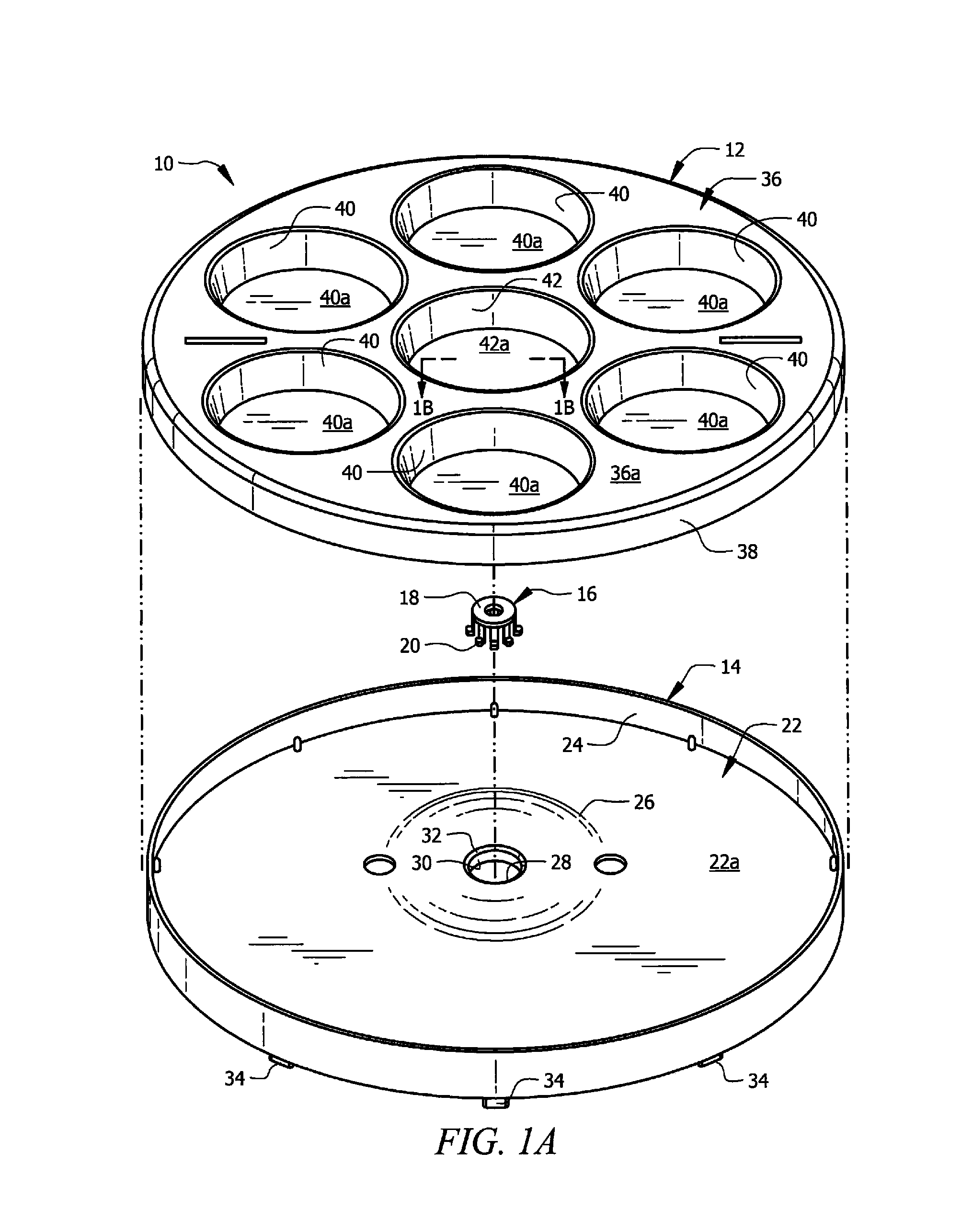
[0039]The novel structure is denoted in FIG. 1 as a whole by the reference numeral 10. Lazy susan 10 includes top part 12 and base or bottom part 14 that are interconnected by interconnecting member 16.
[0040]Interconnecting member 16 has a flat, toroidal part 18 and a plurality of “L”-shaped flexible arms, collectively denoted 20, mounted about the outer periphery of said flat toroidal part 18 in circumferentially and equidistantly spaced relation to one another.
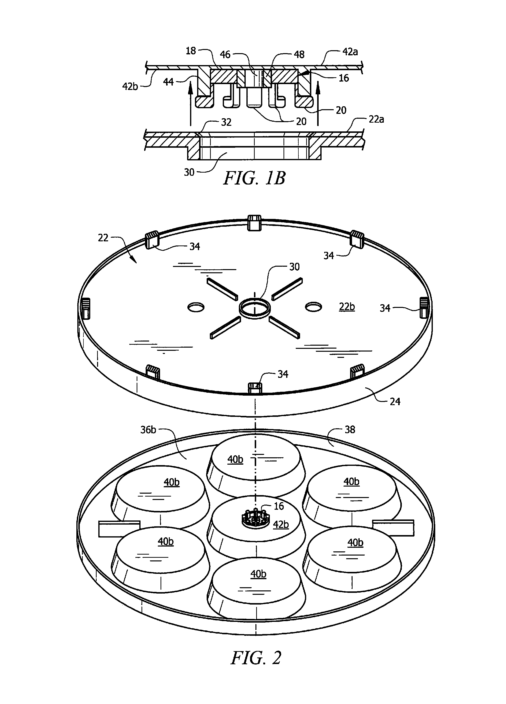
[0041]Base member 14 includes flat, disc-shaped bottom wall 22 that is circumscribed by flange 24. The top surface of wall 22 is denoted 22a and the bottom surface thereof is denoted 22b in the Figures.
[0042]Bulge 26 is formed in the center of wall 22 and central opening 28 is formed in the center of bulge 26 which is also the center of wall 22.
[0043]As depicted in FIG. 1A but as perhaps better understood in connection with FIGS. 1B, 2 and 3, truncate cylindrical wall 30 is formed integrally with and depends from central ope...
PUM
 Abstract
Description
Claims
Application Information
 - R&D
- Intellectual Property
- Life Sciences
- Materials
- Tech Scout
- Unparalleled Data Quality
- Higher Quality Content
- 60% Fewer Hallucinations
Browse by: Latest US Patents, China's latest patents, Technical Efficacy Thesaurus, Application Domain, Technology Topic, Popular Technical Reports.
© 2025 PatSnap. All rights reserved.Legal|Privacy policy|Modern Slavery Act Transparency Statement|Sitemap|About US| Contact US: help@patsnap.com


