Low friction rod persuader

a low friction rod and persuader technology, applied in the field of medical instruments, can solve problems such as unwanted reverse rotation of the drive system, and achieve the effect of less friction

Active Publication Date: 2013-10-01
XTANT MEDICAL HLDG INC
View PDF13 Cites 45 Cited by
  • Summary
  • Abstract
  • Description
  • Claims
  • Application Information

AI Technical Summary

Benefits of technology

[0009]Whereas in prior art ratchet systems a pawl binds against the teeth of a ratchet mechanism to prevent backward motion and requires relief from any load placed upon the teeth prior to pivoting the pawl out of the way to disengage the ratchet mechanism, positioning the ratchet pawl on a moveable ratchet engagement member capable of shifting the entire pawl away from the ratchet teeth advantageously provides the ratchet mechanism with the ability to engage and disengage even when under a heavy load.
[0012]In one aspect of the invention, the reducer instrument may have a clamp member for selectively securing the coupling device to the instrument, a reducer member for shifting the elongate member into place within the coupling device, and optionally a locking member inserter to secure a locking member to the coupling device in order to capture the elongate member therein. One or more of the members, or a separate drive actuator member, may be provided with a helical recess on its inner or outer surface to interact with a rolling element coupled to another member in order to transfer rotational motion of one portion of the instrument into linear motion of the same portion or another portion of the instrument. In this manner, the instrument responds to manipulation in much the same manner as a threaded drive system, although friction is greatly reduced due to the presence of rolling elements instead of complementary threads. The need for lubrication is thereby minimized or eliminated, and cleanability of the instrument is improved since the drive system can be fully sealed.
[0014]The components of the reducer instrument may be generally cylindrical in shape to minimize the profile of the apparatus, reducing the size of the incision necessary for surgery and subsequently reducing the recovery time of the patient. In alternative embodiments, the components can have other configurations such as hexagonal prism or rectangular prism configurations.
[0017]In one preferred form, the reducer instrument includes an elongate stationary clamp member; a rotatable drive actuator operatively coupled to the clamp member; a reducing member operatively coupled to the clamp member and drive actuator so that it is shiftable along the axis of the elongate clamp member; and optionally a cap inserter. In a preferred form, the reducing member includes a sleeve portion surrounding the clamp member, while the drive member is positioned within an axial bore of the clamp member, and has a helical recess about its outer surface. The helical recess of the drive member is sized and configured to receive rolling elements that extend through elongate openings of the clamp member and are linked to the reducing member disposed about the outer surface of the clamp member. Elongate openings in the clamp member may be positioned so as to allow the rolling elements to contact both the helical recess of the drive member and the interior surface of the reducing member even though the clamp member is disposed between the two. In this form, rotation of the drive member guides the rolling elements along the helical recess, shifting them through the elongate opening in the clamp member and, due to their linkage to the reducing member, causing the reducing member to shift along the exterior of the clamp member. In another preferred form, a ratchet assembly is provided in order to allow rotation of the drive member in one direction but prevent rotation of the drive member in the opposite direction unless the ratchet assembly is disengaged.
[0018]The instruments described herein may be adapted for use with particular coupling devices, such as those described in U.S. Pat. No. 7,141,051 (issued on Nov. 28, 2006), U.S. Patent Application 2008 / 0045955 (Ser. No. 11 / 839,843), or U.S. Patent Application 2007 / 0225711 (Ser. No. 11 / 726,868), all of which applications are hereby fully incorporated by reference as if fully set forth herein. The instrument, anchor member, and coupling device may all be fully cannulated so that a wire can be passed therethrough for minimally invasive surgical (MIS) systems. In such systems, a guide wire is attached to a predetermined point on the surface of a bone, and then elements of an implant such as the coupling device mentioned above are passed around the guide wire so that the guide wire directs the implant elements to the predetermined point on the bone. Similarly, the instrument for reducing an elongate member into the coupling device also can be cannulated, i.e. contain a pathway through the center of the tool so that the aforementioned guide wire threaded through the anchor and coupling device can be threaded through the body of the instrument and is able to direct implantation or manipulation of the system without interfering with the operation of the tool. The accuracy gained by use of such a guide wire reduces the amount of tissue affected by the surgical procedure and reduces recovery time for the patient.

Problems solved by technology

The ease of use of the helical drive system described herein may lead to unwanted reverse rotation of the drive system due to the reduced friction involved.

Method used


Image

  • Low friction rod persuader
  • Low friction rod persuader
  • Low friction rod persuader

Examples


Embodiment Construction

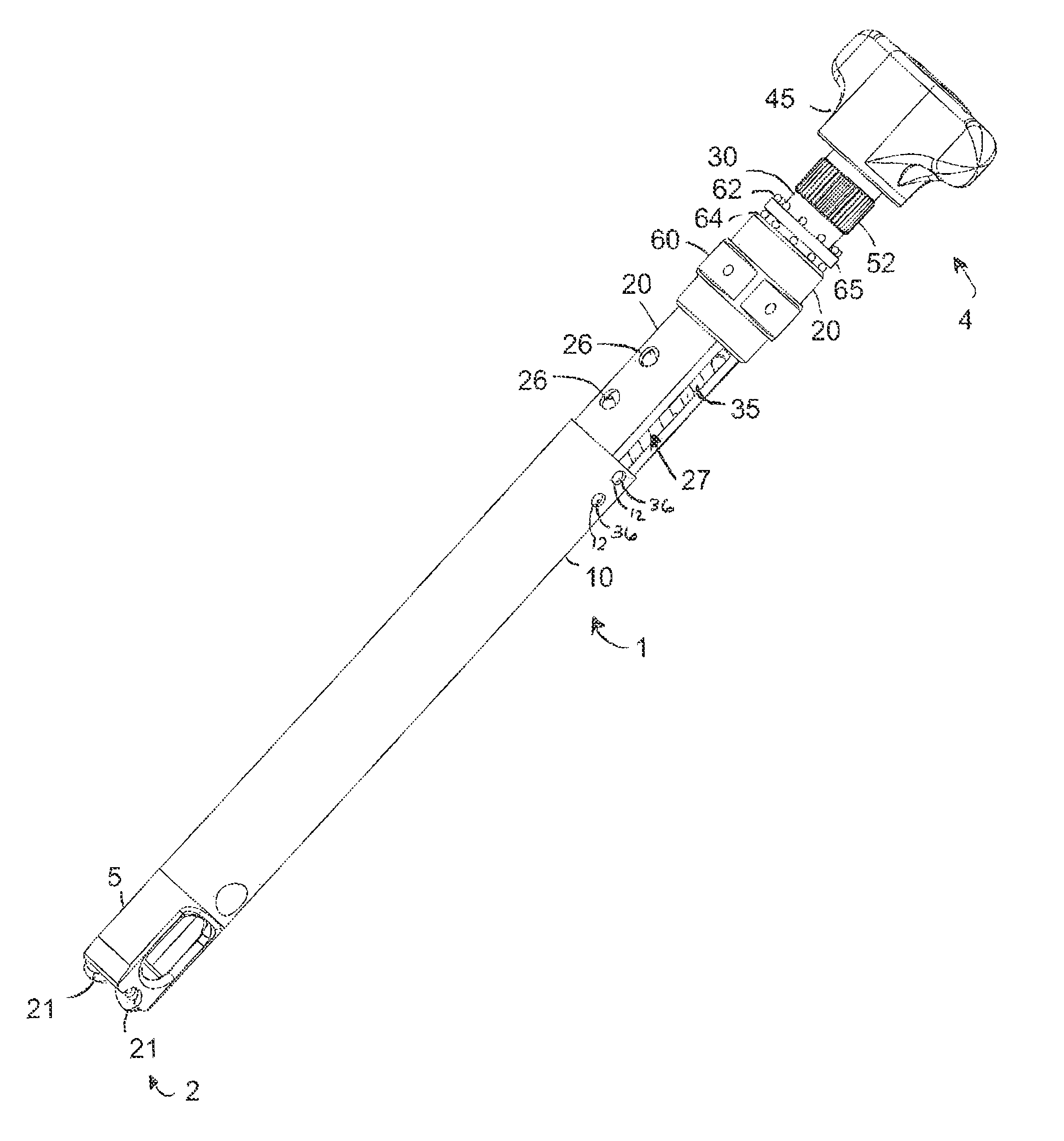
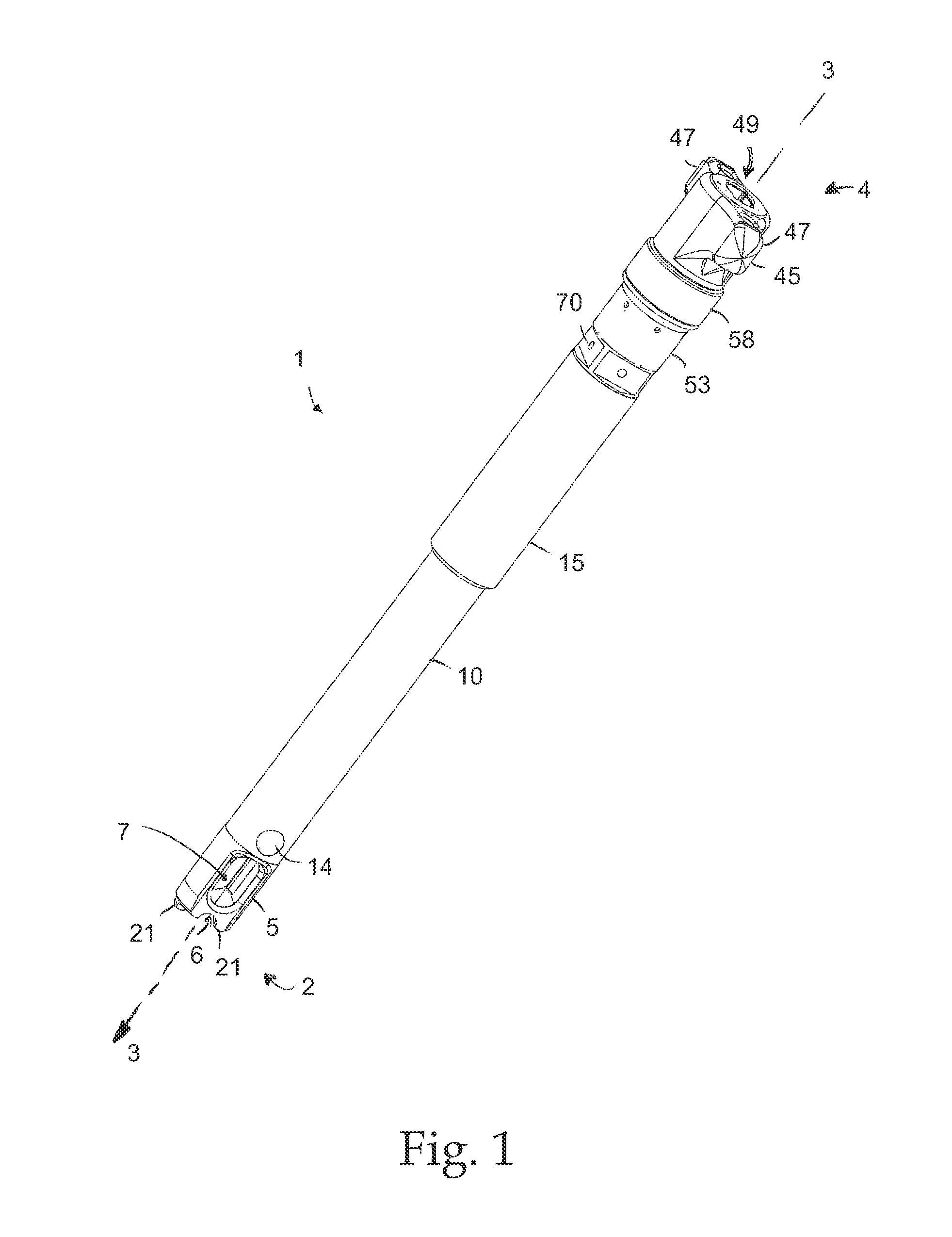
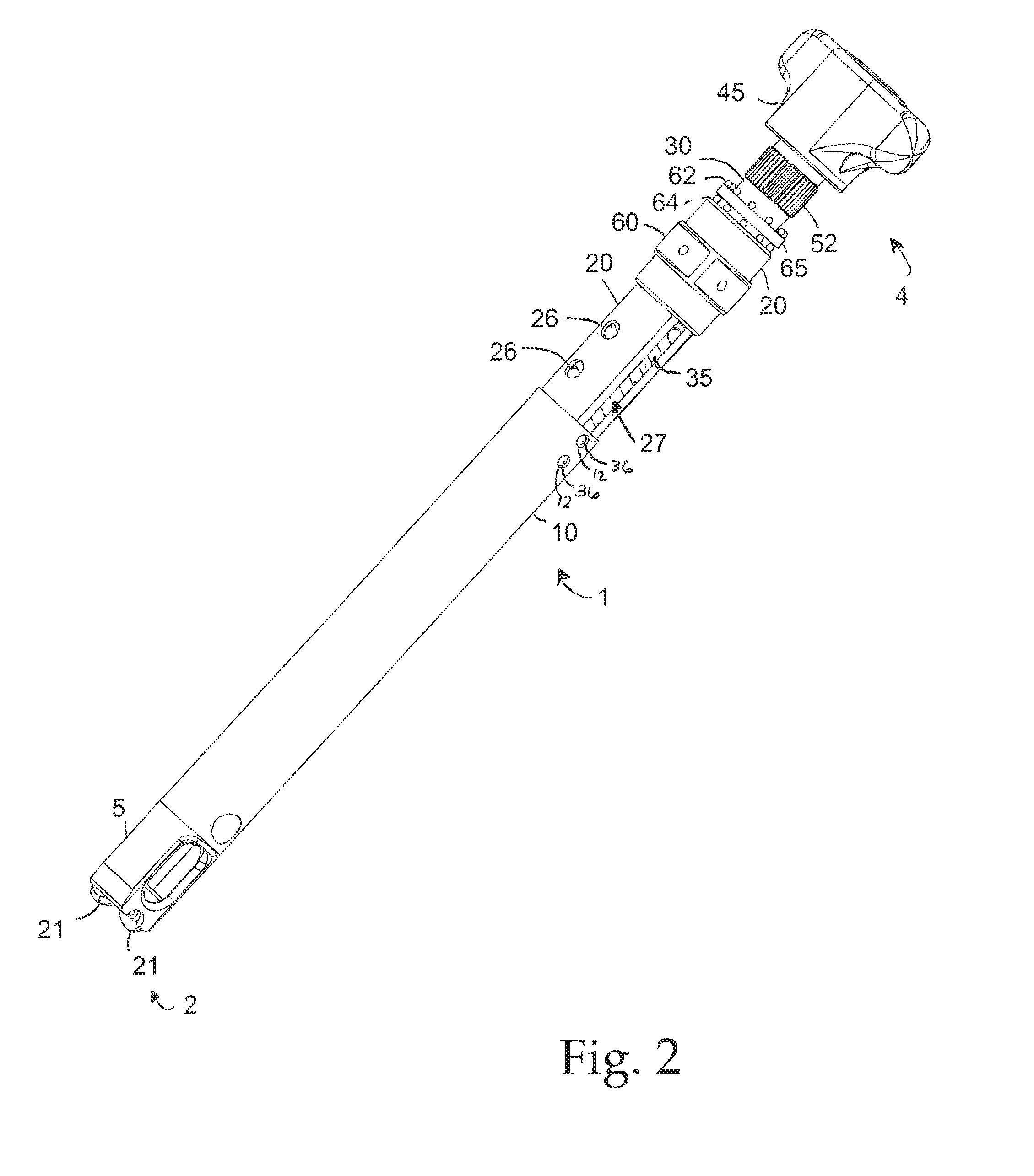
[0032]FIG. 1 illustrates a particular embodiment of the reducer instrument disclosed herein. The exemplary instrument includes a central clamp member with clamping prongs 21 designed to engage a coupling device such as a pedicle screw assembly, a reducer sleeve 10 with a head portion 5 that is contoured to abut a spinal rod and shift the rod along the instrument axis 3, and a rotatable actuator 45 configured to shift the reducer sleeve 10 axially when rotated. Rotatable actuator 45 includes two lateral flanges 47 in order to form a T shape for easy manipulation by a surgeon. A ratchet system, which minimizes or substantially prevents unwanted backward rotation of the handle 45 when engaged, is located within the instrument and hidden from view by a ratchet housing 53 and a ratchet cover 58.

[0033]The reducer head portion 5 of the exemplary instrument includes a reducing surface 6 formed as a semi-cylindrical notch designed to match the contour of the spinal rod to be reduced, and als...


PUM


Abstract

Instruments are provided for shifting elongate members, such as spinal rods, with respect to coupling members of spinal fixation systems. The instruments include a low friction drive mechanism having one or more rolling elements that ride along a helical groove or track in order to transform rotational movement of a drive member into linear shifting of a reducer member that shifts the elongate member. A one-way locking mechanism may be provided to selectively prevent unwanted counter-rotation of the low friction drive mechanism. The one-way locking mechanism may include annular ratchet teeth arranged on the exterior of the drive member and a ratchet pawl located adjacent to the teeth and selectively engageable therewith.

Description

CROSS-REFERENCE TO RELATED APPLICATION[0001]This application claims the benefit of U.S. Provisional Application 61 / 295,625, filed Jan. 15, 2010, which is hereby incorporated herein by reference in its entirety.FIELD OF THE INVENTION[0002]This invention pertains generally to medical instruments and more specifically to spinal implant insertion instruments for spinal fixation systems.BACKGROUND OF THE INVENTION[0003]Various devices for internal fixation of bone segments in the human or animal body are known in the art. One type of system is a pedicle screw system, which is sometimes used as an adjunct to spinal fusion surgery, and which provides a means of gripping a spinal segment. A conventional pedicle screw system comprises a pedicle screw anchor and a rod-receiving device or coupling member. The pedicle screw anchor includes an externally threaded stem or shank and a head portion. The rod-receiving device couples to the head portion of the pedicle screw and receives an elongate m...

Claims


Application Information

Patent Timeline
Patent Type & Authority Patents(United States)
IPC IPC(8): A61B17/70
CPCA61B17/7086A61B17/7085A61B17/7032
Inventor SANDSTROM, JASON P.HOFFMAN, JEFFREY A.VLAHOS, JEFFREY D.
Owner XTANT MEDICAL HLDG INC
Why Eureka
Try Eureka