Optical arrangement for photomanipulation

a technology of optical arrangement and sample, applied in the field of optical arrangement for sample photomanipulation, can solve the problems of high cost, limited device availability, and difficult spatial precision manipulation, and achieve the effect of high cost and large expenditure on conversion

Active Publication Date: 2013-10-01
CARL ZEISS MICROSCOPY GMBH
View PDF5 Cites 10 Cited by
  • Summary
  • Abstract
  • Description
  • Claims
  • Application Information

AI Technical Summary

Benefits of technology

[0015]Therefore, it is the object of the invention to develop an arrangement by which manipulation can be carried out in limited areas of the sample in a simple manner substantially in the focus plane of the microscope. In particular, a confocal manipulation of samples should be possible also without the use of multiphoton effects. The arrangement should advantageously also be capable of three-dimensional, isotropic imaging of the sample before, after, or during the manipulation.
[0023]The advantage in using the arrangement described above is that manipulation remains restricted to the focus plane; outside the focus plane, the sample is not impaired. Another advantage of the described arrangement consists in that the means for photomanipulation can be integrated in existing setups for SPIM analyses in a simple manner, for example, in a modular construction.
[0028]Therefore, when using two manipulation optics, as was just described, whose beam paths intersect substantially perpendicularly in the sample, it is possible to limit the manipulation to a small area of the sample, namely, to the area in which the light beams of the manipulation optics intersect, without a great expenditure on conversion and without high costs. In this way, a confocal sample manipulation is possible without requiring expensive arrangements using multiphoton effects. However, when both manipulation light beams are used, it is also easy to make use of multiphoton effects in the examination.
[0029]A considerable advantage of SPIM technology is the possibility of generating spatial images of the sample. Therefore, the sample and / or the sample holder are / is also advisably supported so as to be movable, preferably rotatable and displaceable, in the present arrangement. In this way, all areas of the sample can be made accessible for manipulation, particularly also for a spatially strictly localized manipulation. The control unit is advisably designed for controlling both manipulation optics. Further, the arrangement advisably has an evaluating unit which converts the light that is preferably detected pixel by pixel on a flat CCD detector into data, i.e., digital signals, and also evaluates it. The signal conversion is often also carried out in the detection device itself. The control unit controls the movement of the sample and / or sample holder, preferably depending on the evaluation of the data. However, when controlled in a corresponding manner, a control according to a given program in which the sample is completely illuminated, for example, and the same manipulation procedures are recurrently carried out is also possible.

Problems solved by technology

However, for spatially extensive, three-dimensional samples, spatially precise manipulation is very difficult and can only be accomplished with complicated setups which are also often based on nonlinear interactions between the manipulation light beam and the sample.
However, there is a limited availability of devices which can carry out a specific manipulation in three-dimensional samples and which allow three-dimensional imaging of the sample at the same time.
However, solutions of this type involve very complicated technology; for example, they require the use of short-pulse lasers and are limited with respect to choice of wavelength.

Method used


Image

  • Optical arrangement for photomanipulation
  • Optical arrangement for photomanipulation
  • Optical arrangement for photomanipulation

Examples


Embodiment Construction

[0035]It is to be understood that the figures and descriptions of the present invention have been simplified to illustrate elements that are relevant for a clear understanding of the present invention, while eliminating, for purposes of clarity, many other elements which are conventional in this art. Those of ordinary skill in the art will recognize that other elements are desirable for implementing the present invention. However, because such elements are well known in the art, and because they do not facilitate a better understanding of the present invention, a discussion of such elements is not provided herein.

[0036]The present invention will now be described in detail on the basis of exemplary embodiments.

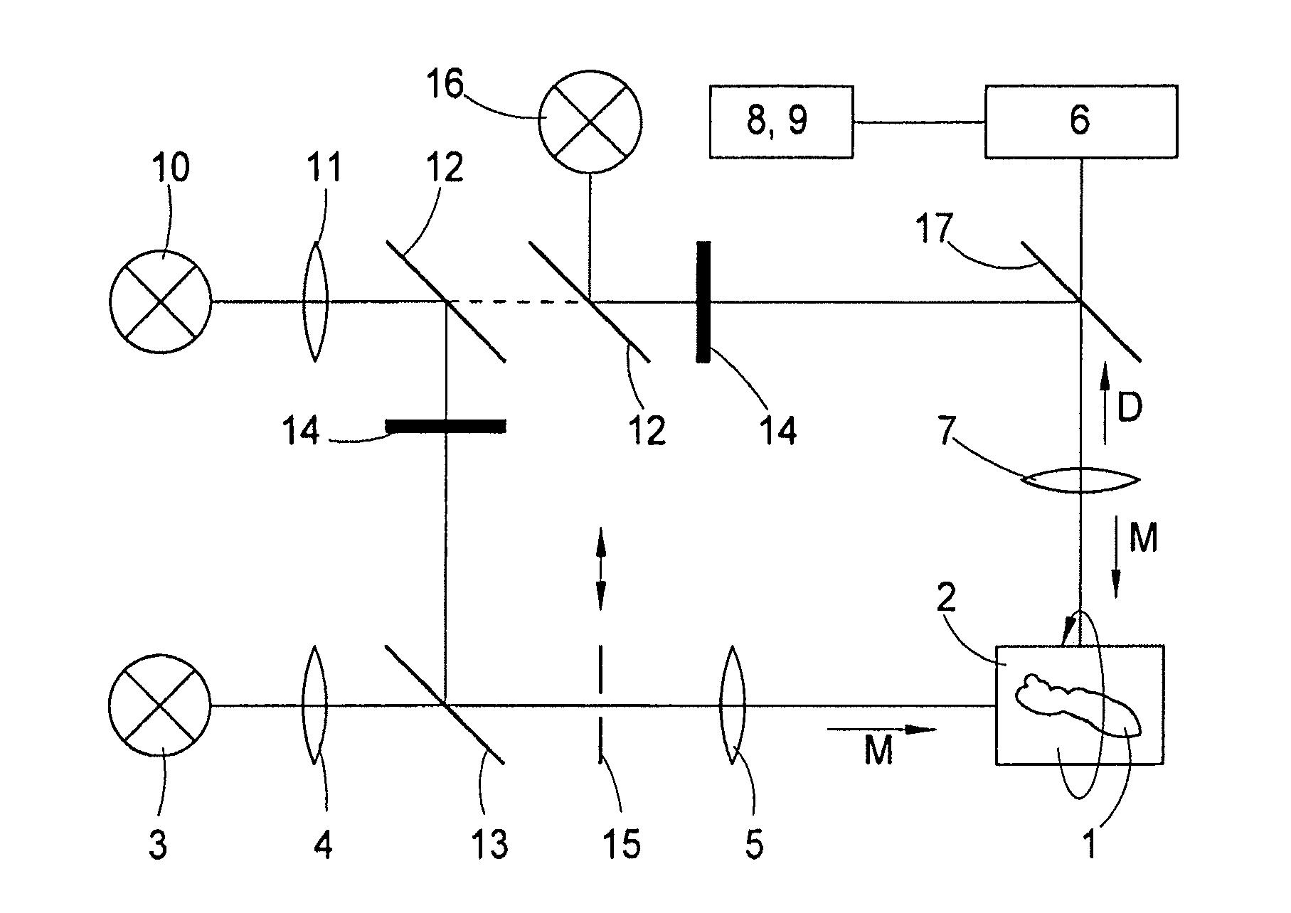
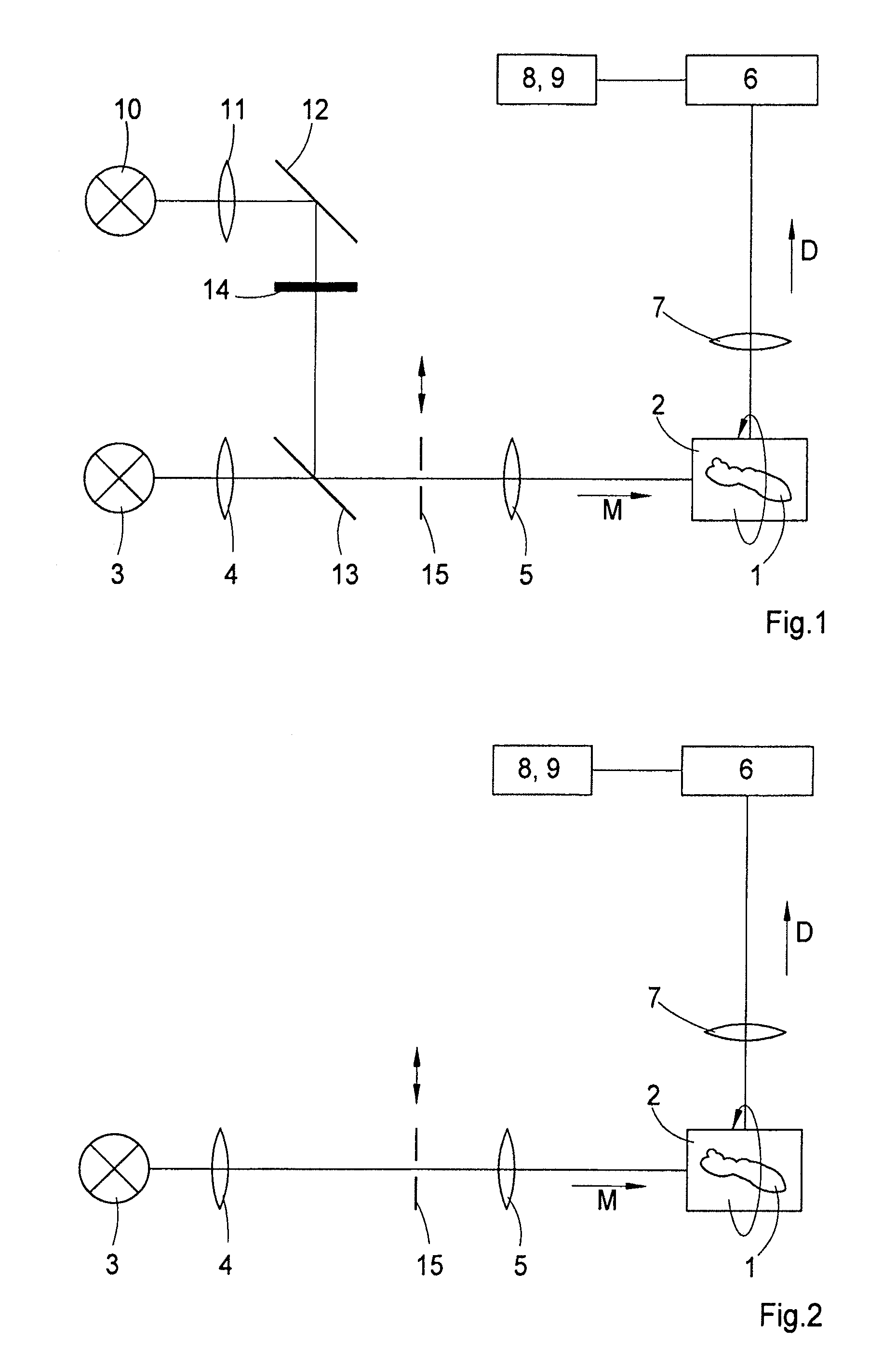
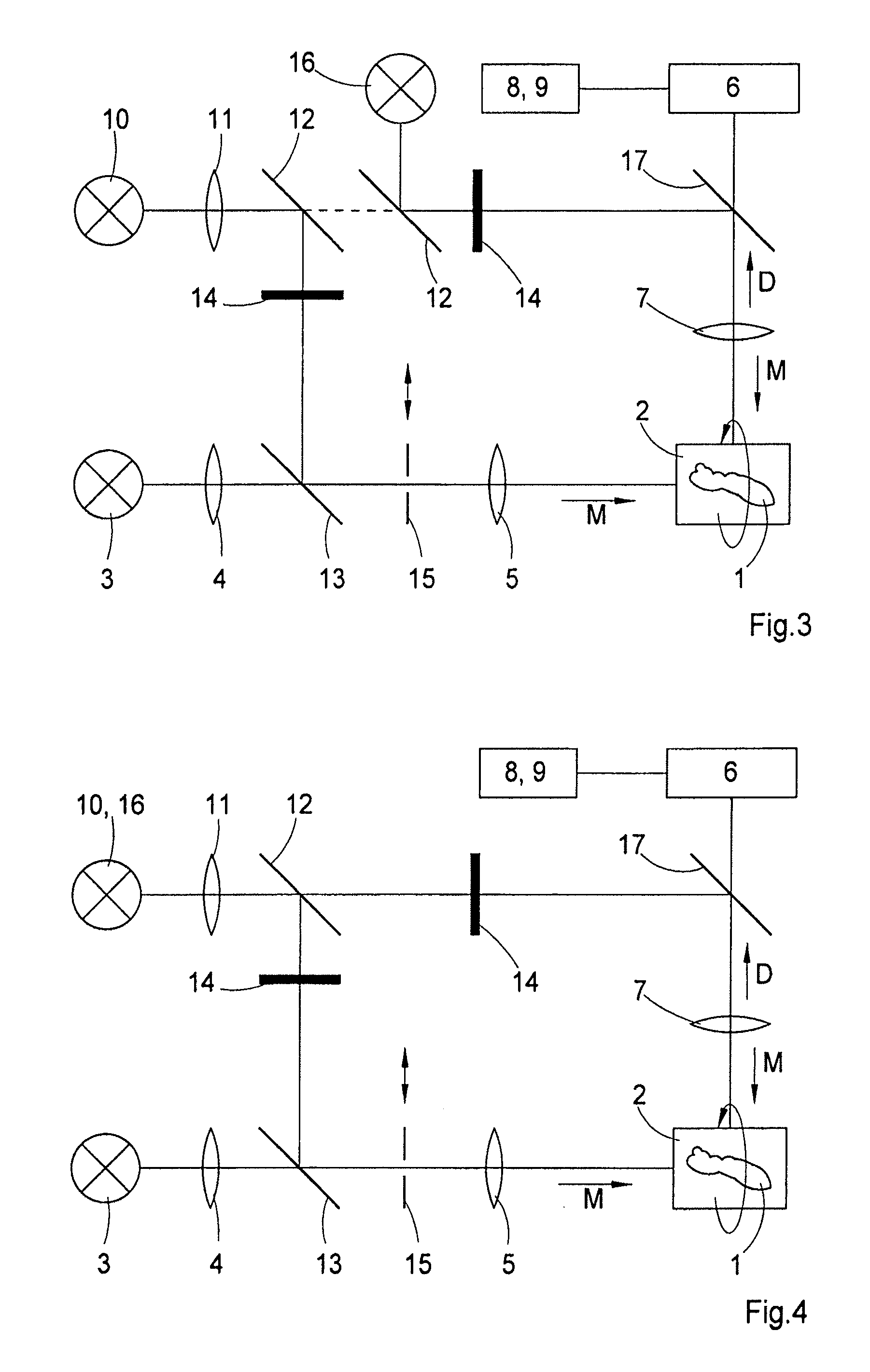
[0037]FIG. 1 shows an optical arrangement for photomanipulation of a sample 1. The sample 1 is received by a sample holder 2. The sample 1 can be embedded, for example, in a gel cylinder of agarose which is fastened in the sample holder 2. The sample holder 2 is preferably supp...


PUM


Abstract

The invention is directed to an optical arrangement for photomanipulation of a sample comprising a sample holder for receiving the sample, an illumination device comprising an illumination light source and an illumination beam path for illuminating the sample with a light sheet. It further comprises a detection device for detecting light that is radiated from the sample and imaging optics which image the sample on the detection device by means of an imaging objective in an imaging beam path, wherein the light sheet is substantially planar in the focus of the imaging objective, and wherein the imaging objective has an optical axis which intersects the plane of the light sheet at an angle different from zero. Further, the arrangement also has means for photomanipulation of the sample.

Description

[0001]The present application claims priority from PCT Patent Application No. PCT / EP2008 / 007690 filed on Sep. 16, 2008, which claims priority from German Patent Application No. 10 2007 047 464.6 filed on Sep. 28, 2007, the disclosure of which is incorporated herein by reference in its entirety.BACKGROUND OF THE INVENTION[0002]1. Field of the Invention[0003]The invention is directed to an optical arrangement for photomanipulation of a sample comprising a sample holder for receiving the sample, an illumination device comprising an illumination light source and an illumination beam path for illuminating the sample with a light sheet, a detection device for detecting light that is radiated from the sample, imaging optics which image the sample at least partially on the detection device by means of an imaging objective in an imaging beam path, wherein the light sheet is substantially planar in the focus of the imaging objective, and wherein the imaging objective has an optical axis which...

Claims


Application Information

Patent Timeline
Patent Type & Authority Patents(United States)
IPC IPC(8): G02B21/06
CPCG02B21/32G02B21/0032
Inventor POWER, CHRISTOPHERLIPPERT, HELMUTRADT, BENNODIETRICH, CHRISTIAN
Owner CARL ZEISS MICROSCOPY GMBH
Why Eureka
Try Eureka