Drilling method

a drilling method and directional drilling technology, applied in drilling pipes, directional drilling, borehole/well accessories, etc., can solve the problems of frequency lateral vibration, reverse bending stress, backward or chaotic whirl, etc., to prevent the initiation of a stick-slip cycle, dampen the stick-slip effect, and high rotational speed and vibration

Active Publication Date: 2013-10-08
NAT OILWELL VARCO LP
View PDF38 Cites 6 Cited by
  • Summary
  • Abstract
  • Description
  • Claims
  • Application Information

AI Technical Summary

Benefits of technology

[0016]Surprisingly, intentionally induced forward whirl results in little if any reduction in drilling efficiency compared to a non-whirl condition, and forward whirl may be induced and maintained with an unexpected degree of stability while simultaneously avoiding or minimizing the occurrence of other forms of whirl, stick slip, and undesirable forms of vibration. The occurrence of forward whirl may be encouraged by a number of steps, as will be described.
[0035]As will be described, an advantageous effect may be achieved by utilizing an aspect of the present invention to increase the effectiveness and cutting efficiency of a hole-opening device. Certain embodiments of this aspect of the invention may be eccentric or bi-center and utilized where it may be desired to open a bore to a diameter greater than the internal diameter of casing above the unlined bore. In one of these embodiments, the hole-opening device is provided above a pilot section of the drill string and is intended to increase the diameter of a pilot hole. The hole-opening device includes a reaming section or wing which sweeps the wellbore. Conventionally, it is intended and assumed that the pilot section and the reaming section will rotate about a common axis, coincident with the axis of the bore being drilled. However, it is difficult to stabilize such devices and hole-opening operations often suffer from unwanted and detrimental vibrations, significantly reducing drilling efficiency and casting uncertainty on the form of the drilled hole. The cutting action of the reaming wing is resisted by the formation and the findings of the present inventors suggest that the resulting reactive force will tend to push the device across the well bore, inducing chaotic or backward whirl, and reducing the lateral cutting force exerted by the device. If, however, the center of mass of the device, or the center of mass of the bottom hole assembly (BHA) associated with the device, is offset in the bore in the direction of the reaming wing, the centripetal force created by rotating the device will tend to maintain the reaming wing in contact with the formation, and resist reactive forces which would otherwise tend to push the device off the formation or into backwards whirl.

Problems solved by technology

Backward or chaotic whirl are very damaging to BHA components, and are associated with high frequency lateral vibrations and reverse bending stresses.

Method used


Image

  • Drilling method
  • Drilling method
  • Drilling method

Examples


Embodiment Construction

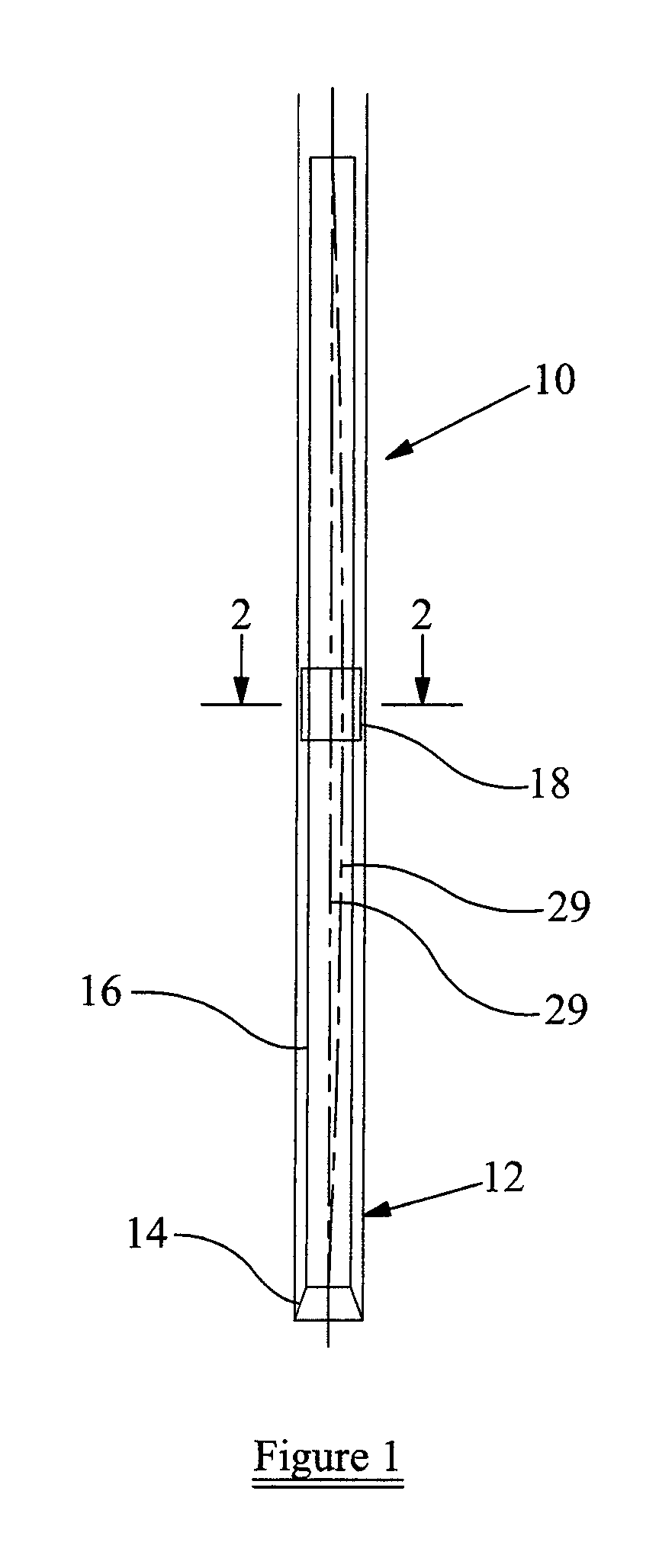
[0050]FIG. 1 illustrates the distal or leading end of a drill string 10, configured in accordance with an embodiment of the present invention. The string 10 features a bottom hole assembly (BHA) 12 including a drill bit 14 and drill collars 16. A stabilizer in the form of a device 18 for inducing and maintaining forward whirl is incorporated in the string above the BHA 12.

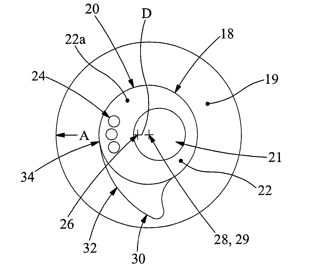
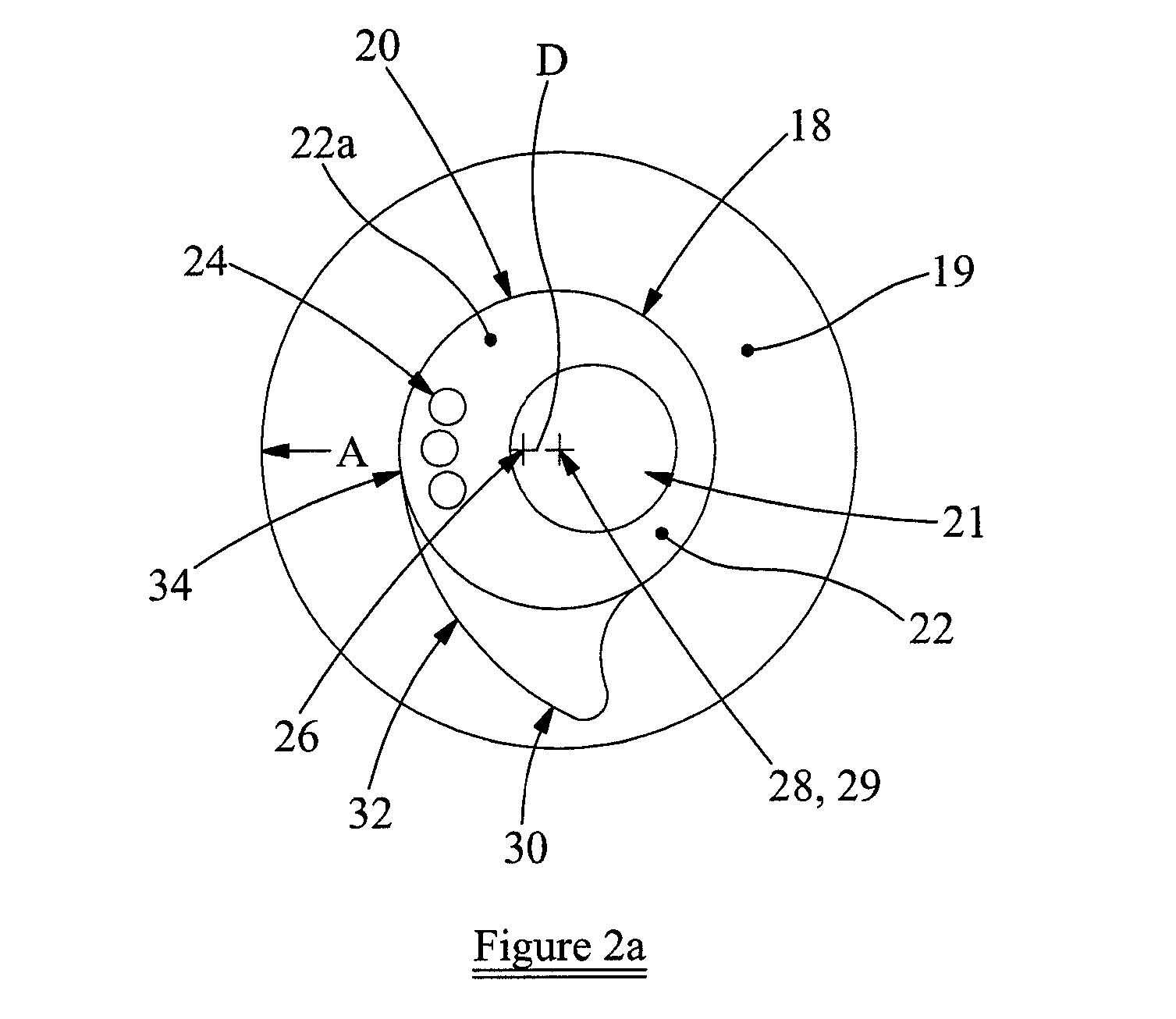
[0051]Reference is also made to FIG. 2a of the drawings, which illustrates the device 18 in cross section, centrally located in the bore 19. The device 18 features a circular mandrel 20 defining a through bore 21 and a surrounding wall 22. The bore 21 is offset to one side of the mandrel 20 and thus one side of the wall 22a is thicker than the other, the thicker side also including high density inserts 24. Thus, the center of mass 26 of the device 18 is offset, by distance D, and in the direction of arrow A, from the axis 28 of the bore 19, which in FIG. 2a coincides with the mandrel and drill string axis 29.

[0052]...


PUM


Abstract

A drilling method comprises controlling operation of a drill string to maintain at least a portion of the drill string in forward whirl.

Description

CROSS-REFERENCE TO RELATED APPLICATIONS[0001]This application claims priority from GB Patent applications: GB 0818499.6 filed on Oct. 9, 2008; and GB 0916033.4 filed on Sep. 14, 2009.BACKGROUND OF THE INVENTION[0002]1. Field of the Invention[0003]This invention relates to a drilling method, such as is used to access subsurface formations. In particular, the invention relates to methods and apparatus to facilitate the avoidance of undesirable vibration or other forms of movement in the drilling apparatus.[0004]2. Description of the Related Art[0005]Bores may be drilled into the earth for a number of reasons, for example to access aquifers or hydrocarbon-bearing formations. Conventionally, drilling is achieved by mounting a drill bit on the leading or distal end of an elongate support, which may take the form of a drill string. The drill bit may be driven by rotating the drill string by a surface motor, or by using a downhole motor. Drill bits take many different forms, and may be ope...

Claims


Application Information

Patent Timeline
Patent Type & Authority Patents(United States)
IPC IPC(8): E21B7/00E21B7/24
CPCE21B7/24E21B17/1078E21B10/00E21B17/16
Inventor FORSTER, IANEDDISON, ALANMACFARLANE, ALASTAIR
Owner NAT OILWELL VARCO LP
Why Eureka
Try Eureka