Multi-layered stents and methods of implanting

a stent and multi-layer technology, applied in the field of stents, can solve the problems of increasing the chance of a stent fracture occurring, affecting the normal functioning of the heart, and affecting the safety of patients, so as to promote or limit tissue ingrowth, limit or prevent the effect of restocarditis, platelet pannus, and/or thrombosis

Inactive Publication Date: 2010-07-15
RYAN TIMOTHY R +3
View PDF13 Cites 77 Cited by
  • Summary
  • Abstract
  • Description
  • Claims
  • Application Information

AI Technical Summary

Benefits of technology

[0016]One or more of the stents of a multi-stent structure can include a complete or partial covering, if desired. In particular, a covering or partial covering can be provided on the outer surface of the outermost stent of a multi-stent structure, and/or on the inside surface of the innermost stent of a multi-stent structure, and/or in between any or all layers of a multi-layer stent structure. Such a covering can be provided to impart some d...

Problems solved by technology

For example, stent fracture is a recognized complication that can occur following stent implantation in cardiovascular applications, which can result in disruption of the normal functioning of the heart.
Certain factors and combinations of factors can increase the chances of a stent fracture occurring, such as choosing a stent wire size that is not appropriate for a stent that is subjected to relatively severe structural loading conditions, the application of high stresses, and other factors.
However, the stresses encountered by such products can be extreme.
This can result in failure of some stents, as is described in U.S. Patent Application Publication No. 2005/0251251.
This publication also recognizes the problems caused by stent recoil in these relatively weak stents that do not allow the stents to be forcefully imbedded into an aortic annulus and the risks o...

Method used


Image

  • Multi-layered stents and methods of implanting
  • Multi-layered stents and methods of implanting
  • Multi-layered stents and methods of implanting

Examples


Embodiment Construction

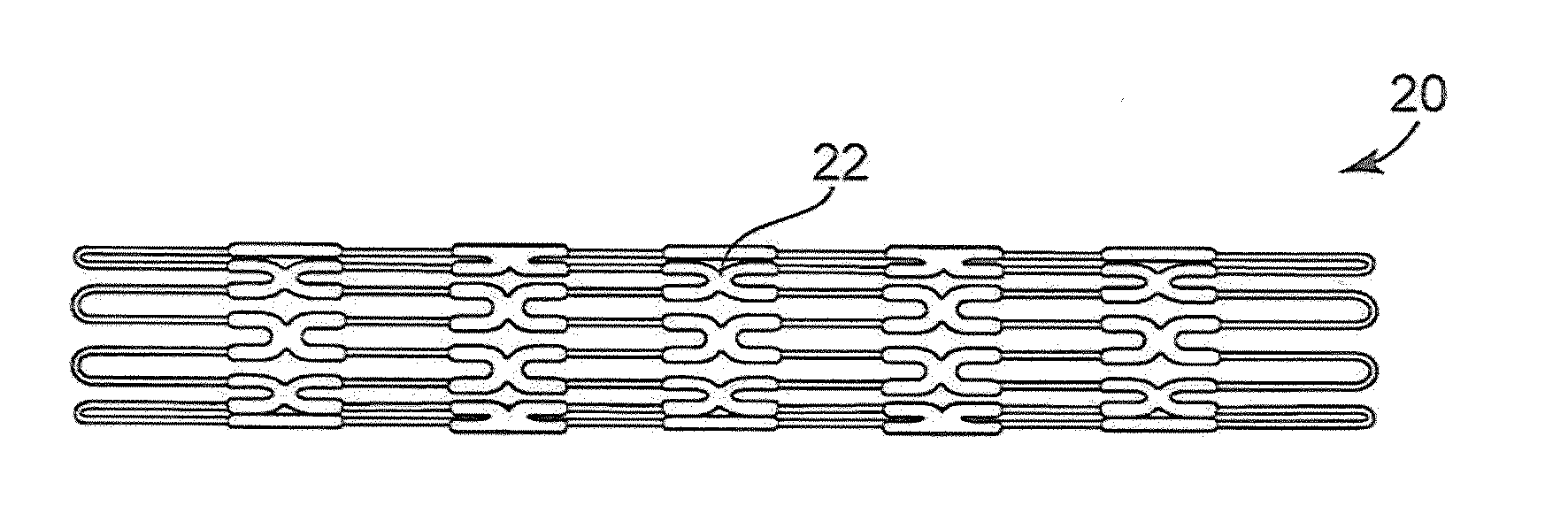
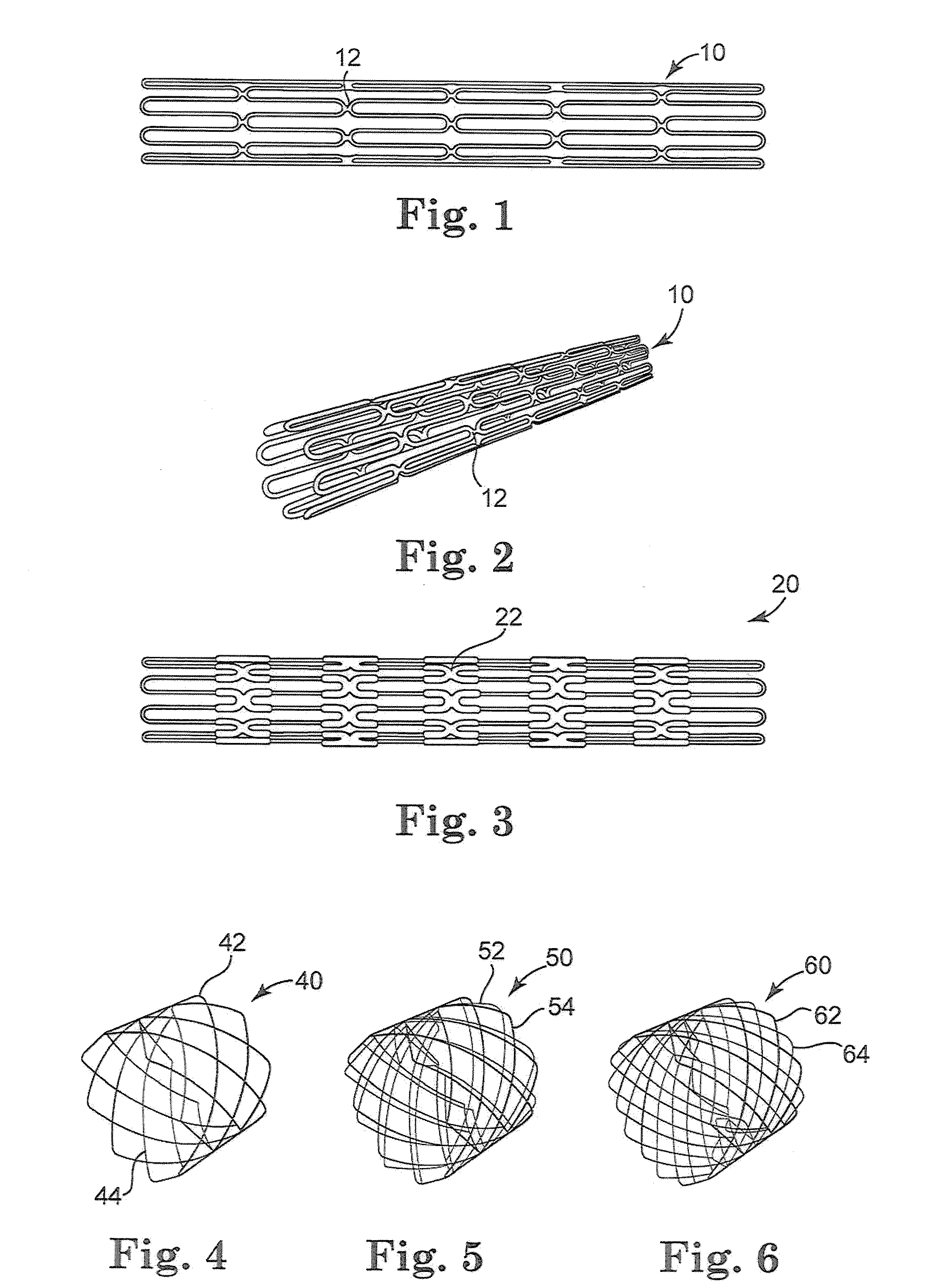
[0033]The properties of stents involved in the design of multi-layered stent constructions of the invention, which may be used for percutaneous pulmonary valve implantation, for example, desirably involve a compromise between interrelated and sometimes contradictory material and geometric properties of multiple stents. That is, the designs and materials selected for each of the stents of the multiple stent structures of the present invention are independently chosen to achieve certain desired overall performance characteristics for the stent. While the description and figures contained herein are primarily directed to two-layered stents, it is understood that multiple-layered stent structures having three or more stents are also contemplated by the invention, where some or all of the stents may be attached or connected in some way to at least one adjacent stent.

[0034]Referring now to the Figures, wherein the components are labeled with like numerals throughout the several Figures, a...


PUM

PropertyMeasurementUnit
Fractionaaaaaaaaaa
Fractionaaaaaaaaaa
Fractionaaaaaaaaaa

Abstract

A method of percutaneously delivering a multi-layered stent assembly to a desired implantation location of a patient including the steps of radially compressing a multi-layered stent assembly to a compressed size for implantation in a patient, the multi-layered stent assembly including a first stent, a second stent coaxially positioned within at least a portion of a length of the first stent, and a valve, wherein the first stent comprises at least one different material property than the second stent. The method further includes delivering the multi-layered stent assembly to the desired implantation location of the patient using a delivery system and substantially simultaneously expanding the first stent and the second stent of the multi-layered stent assembly at the desired implantation location to a radially expanded size that is larger than the compressed size.

Description

PRIORITY CLAIM[0001]This application is a divisional application of U.S. application Ser. No. 12 / 070,208, filed Feb. 15, 2008, entitled “MULTI-LAYERED STENTS AND METHODS OF IMPLANTING,” now pending, which claims the benefit of United States Provisional patent application having Ser. No. 60 / 901,582, filed Feb. 15, 2007, and titled “Multi-Layered Stents and Methods of Implanting”, the entire contents of which are incorporated herein by reference in its entirety.TECHNICAL FIELD[0002]The present invention relates to stents used in the treatment of cardiac and venous valve disease. More particularly, it relates to minimally invasive and percutaneous implantation of stents in the treatment of cardiac and venous valve disease.BACKGROUND[0003]Stents are commonly used for treatment of a wide variety of medical conditions; Stent fractures are a phenomenon to be avoided, particularly when such fractures are so numerous and / or severe that they disrupt or destroy the functioning of the stent. Fo...

Claims


Application Information

Patent Timeline
IPC IPC(8): A61F2/82A61F2/90
CPCA61F2/2418A61F2230/0054A61F2/90A61F2/915A61F2250/0015A61F2250/0018A61F2250/006A61F2/852A61F2/958A61F2002/826A61F2002/828A61F2240/001A61F2210/0076A61F2220/0008A61F2220/0016A61F2220/0025A61F2220/0058A61F2/2475Y10T29/49
Inventor RYAN, TIMOTHY R.LASKE, TIMOTHY G.BONHOEFFER, PHILIPPSCHIEVANO, SILVIA
Owner RYAN TIMOTHY R
Why Eureka
Try Eureka