System for supplying components

a supply system and component technology, applied in the direction of control devices for conveyors, conveyor parts, conveyors, etc., can solve the problems of lack of efficiency, poor mastery of small components, and inability to use supply systems traditionally used for components of average to large size, so as to improve the percentage of correctly oriented components and control the distribution of components

Active Publication Date: 2013-10-08
ASYRIL
View PDF31 Cites 24 Cited by
  • Summary
  • Abstract
  • Description
  • Claims
  • Application Information

AI Technical Summary

Benefits of technology

[0012]The vibrations of the plate in the three directions make it possible to better control the distribution of the components on its surface and to increase the percentage of correctly oriented components.

Problems solved by technology

However, the process of supplying small components, smaller than 3 mm2, is still very poorly mastered and is left largely to chance.
These “parasitic” forces cause “adhesion” of the components to each other or against the surrounding surfaces, such that the supply systems traditionally used for components of average to large size cannot be used in the field of small components.
However, these systems lack efficiency and do not make it possible to supply the robot suitably when it involves transporting small components.
However, the movement of the components between the storage reservoir, the recirculation element and the vibrating plate is due solely to gravity, the storage reservoir and the recirculation element having downwardly slanted walls.
Such a device therefore requires a larger bulk due to the place taken up by the slanted storage reservoir.
Moreover, it cannot be used when the transport of the components is done using a linear conveyor, the components not being able to move by gravity between the conveyor and the recirculation element.
More particularly, the support member is a plate that vibrates with six degrees of freedom, under the action of eight linear actuators arranged so as to exert forces and torques on the plate in arbitrary directions at all times. This system has the drawbacks of being complex and bulky.
Moreover, it has the drawback of generating, in all cases, at least one rotation of the surface of the support member.
On the other hand, if they are remote, they will undergo great acceleration.
This effect is harmful in the context of a supply of components for which one seeks to act on the entire surface with the same vibrational effects so as to have homogenous behavior of the components.

Method used


Image

  • System for supplying components
  • System for supplying components
  • System for supplying components

Examples


Embodiment Construction

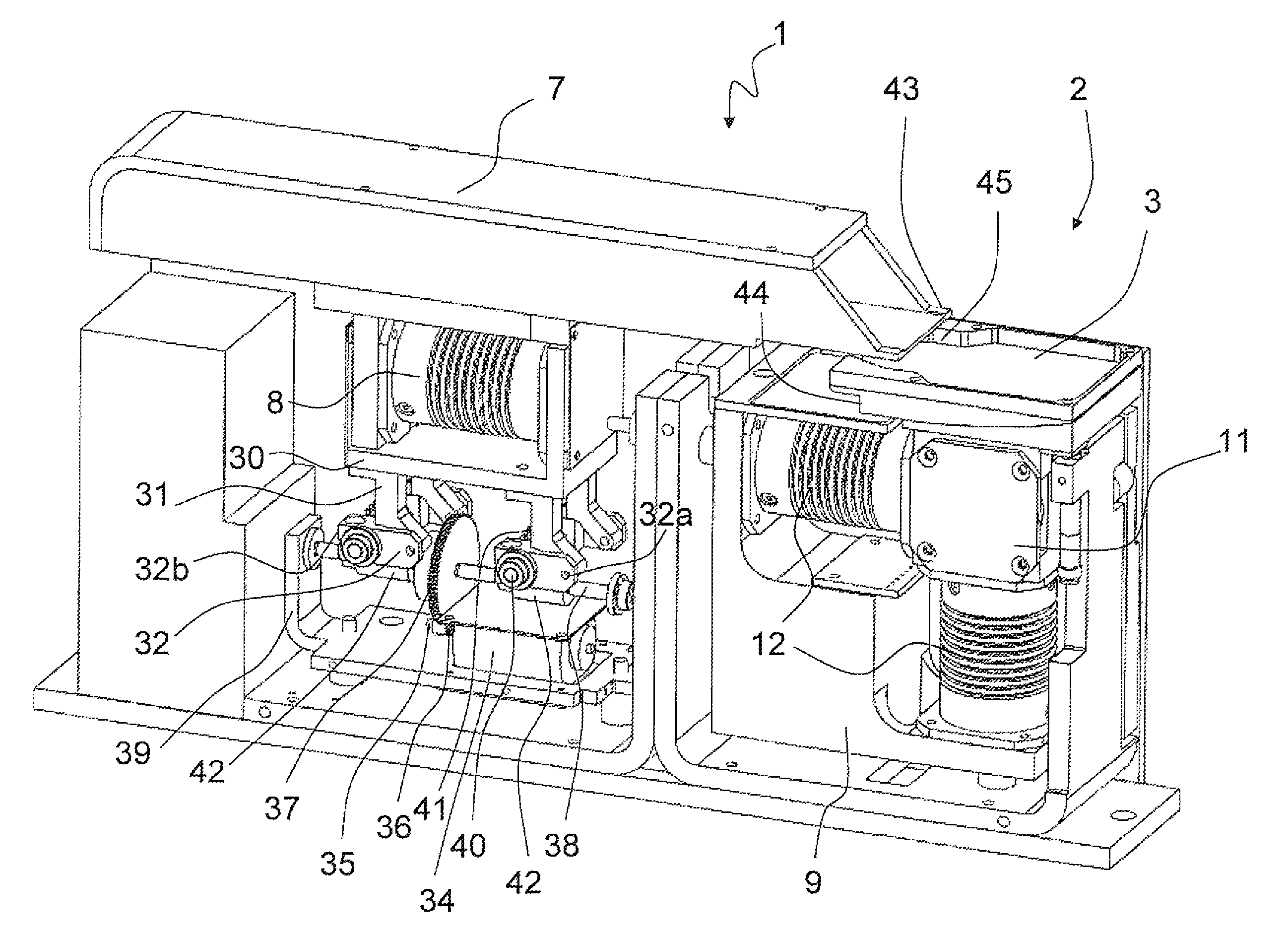
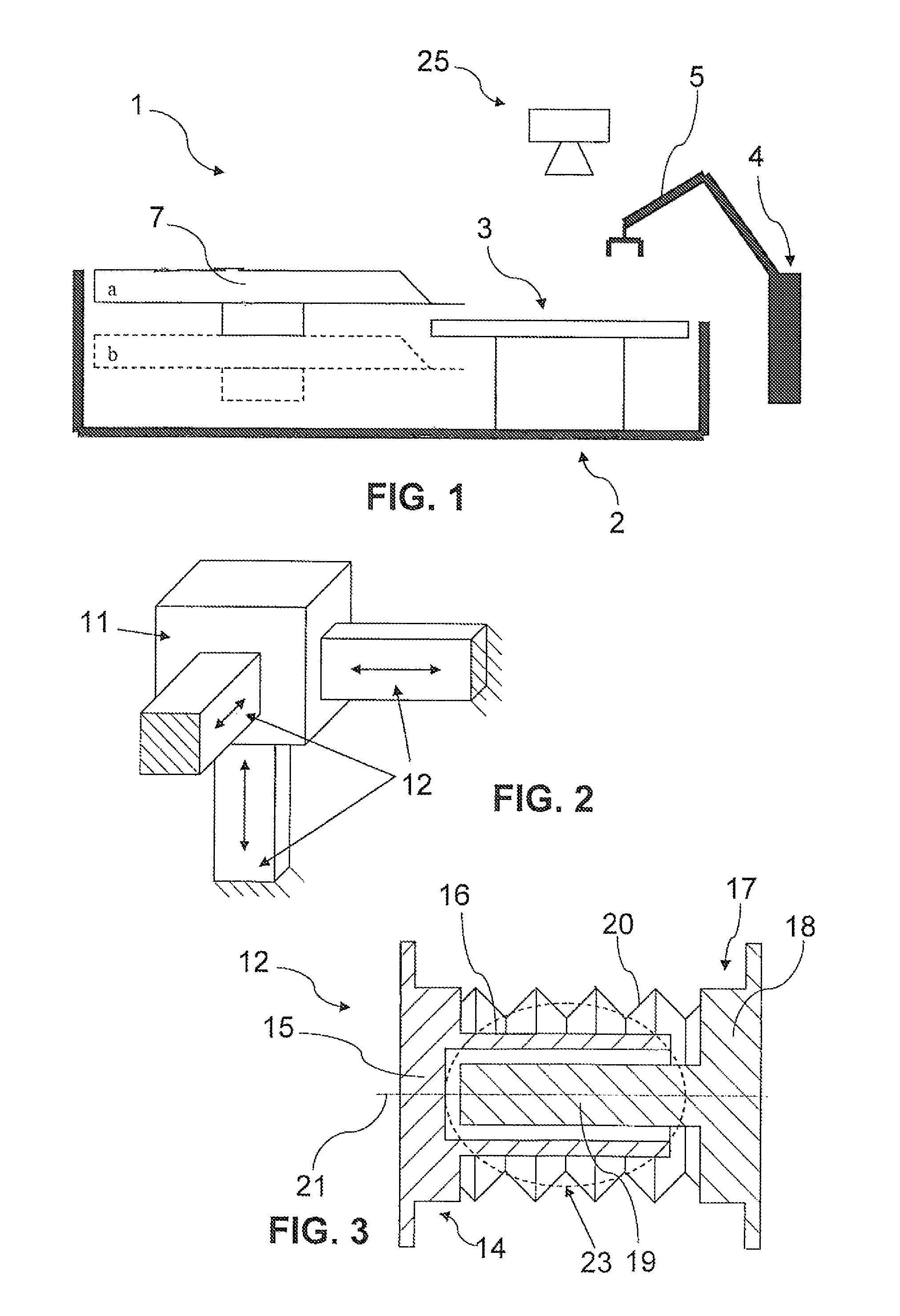
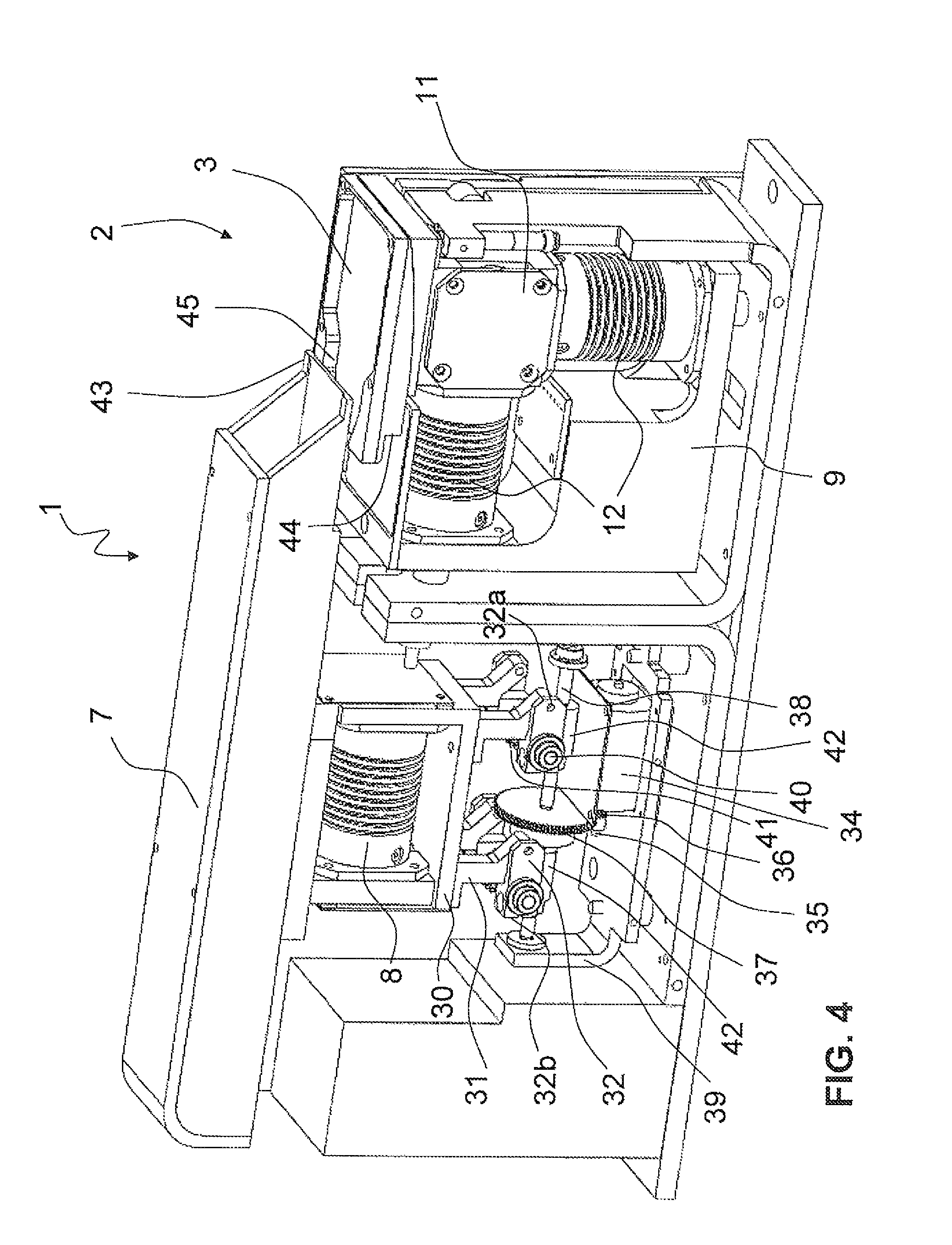
[0032]In reference to FIGS. 1 and 4, a supply system 1 is shown for supplying components stored in bulk in a silo (not shown). Said supply system 1 comprises a vibrating device 2 equipped with a plate 3 making up a surface for enabling the components to be grasped by a robot 4 equipped with a hinged handling arm 5. To convey the components stored in the silo onto the plate 3, the supply system 1 comprises a conveyor 7, independent from the vibrating device 2. More specifically, the conveyor 7 is separated from the plate 3.

[0033]In the illustrated alternative, the conveyor 7 is a linear conveyor set in motion by a linear vibrator 8. Such a linear vibrator is known in itself and does not call for additional description. Of course any other type of conveyor, independent of the vibrating device and separate from the plate, can be used to conveyor the components onto the plate 3. The conveyor 7 can be mounted removably so that it can be disassembled and serve as a storage reservoir.

[0034...


PUM


Abstract

A system (1) for supplying components, particularly for transporting small components includes a vibrating device (2) provided with a plate (3) forming a surface for enabling the components to be grasped by a robot and a vibrating element (12) arranged to be capable of vibrating the plate (3) in one of the three directions in space and to be capable of vibrating the plate (3) in directions corresponding to any combination whatsoever of the three directions x, y and z. For this purpose, the vibrating element includes vibrating actuators (12) respectively including a vibrating element arranged to move with at least five degrees of freedom.

Description

TECHNICAL FIELD[0001]The present invention relates to a system for supplying components comprising a vibrating device provided with a plate forming a surface for enabling the components to be grasped by a robot and a vibrating means arranged to be capable of vibrating said plate.BACKGROUND OF THE INVENTION[0002]Such a system can be used to transport components to a robot comprising a handling arm, which will grasp the components on the plate. In many fields, such as electronics or horology, the components are conveyed in bulk on assembly lines. To be able to use them in an automated process, it is necessary to provide a supply system. Supply systems already exist for components of average to large size (>3 mm2), such as vibrating bowls or centrifuges. However, the process of supplying small components, smaller than 3 mm2, is still very poorly mastered and is left largely to chance. This comes from the fact that the stresses and forces present for the small components, such as cap...

Claims


Application Information

Patent Timeline
Patent Type & Authority Patents(United States)
IPC IPC(8): B65G27/34
CPCB65G27/34
Inventor PERROUD, SEBASTIENHAFNER, TOBIASMUSSARD, YVES
Owner ASYRIL
Why Eureka
Try Eureka