Fluid fitting for soft tubing

a technology for soft tubing and fittings, which is applied in the direction of hose connections, manufacturing tools, mechanical apparatus, etc., can solve the problems of reducing the laminar flow of fluid, and achieve the effect of high temperature capability and cost-effective structur

Active Publication Date: 2013-10-08
DESIGNED METAL CONNECTIONS
View PDF11 Cites 4 Cited by
  • Summary
  • Abstract
  • Description
  • Claims
  • Application Information

AI Technical Summary

Benefits of technology

[0005]The present invention provides a fluid fitting with a high temperature capability for connecting tubes by axially swaging a swaging ring. The fluid fitting includes first and second sleeves and a swage ring. An annular space between the first and second sleeves receives an end of a tube for axial swaging. The inventive fluid fitting advantageously applies an axial swaging force instead of a compressive radial force and is provided in a compact, cost-effective structure.

Problems solved by technology

However, this structure reduces the laminar flow of fluid.

Method used


Image

  • Fluid fitting for soft tubing
  • Fluid fitting for soft tubing
  • Fluid fitting for soft tubing

Examples


Embodiment Construction

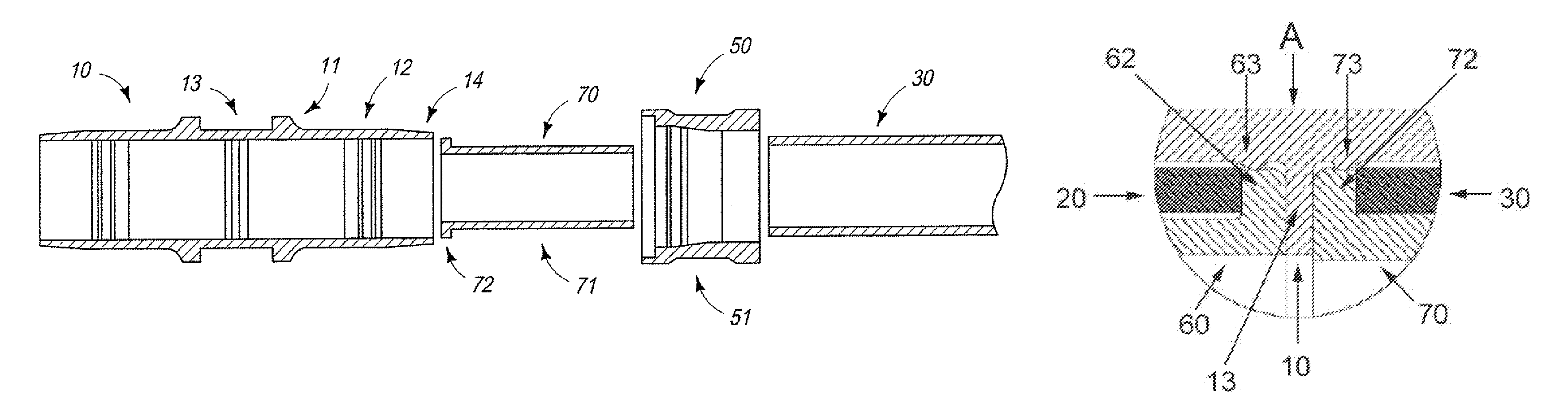
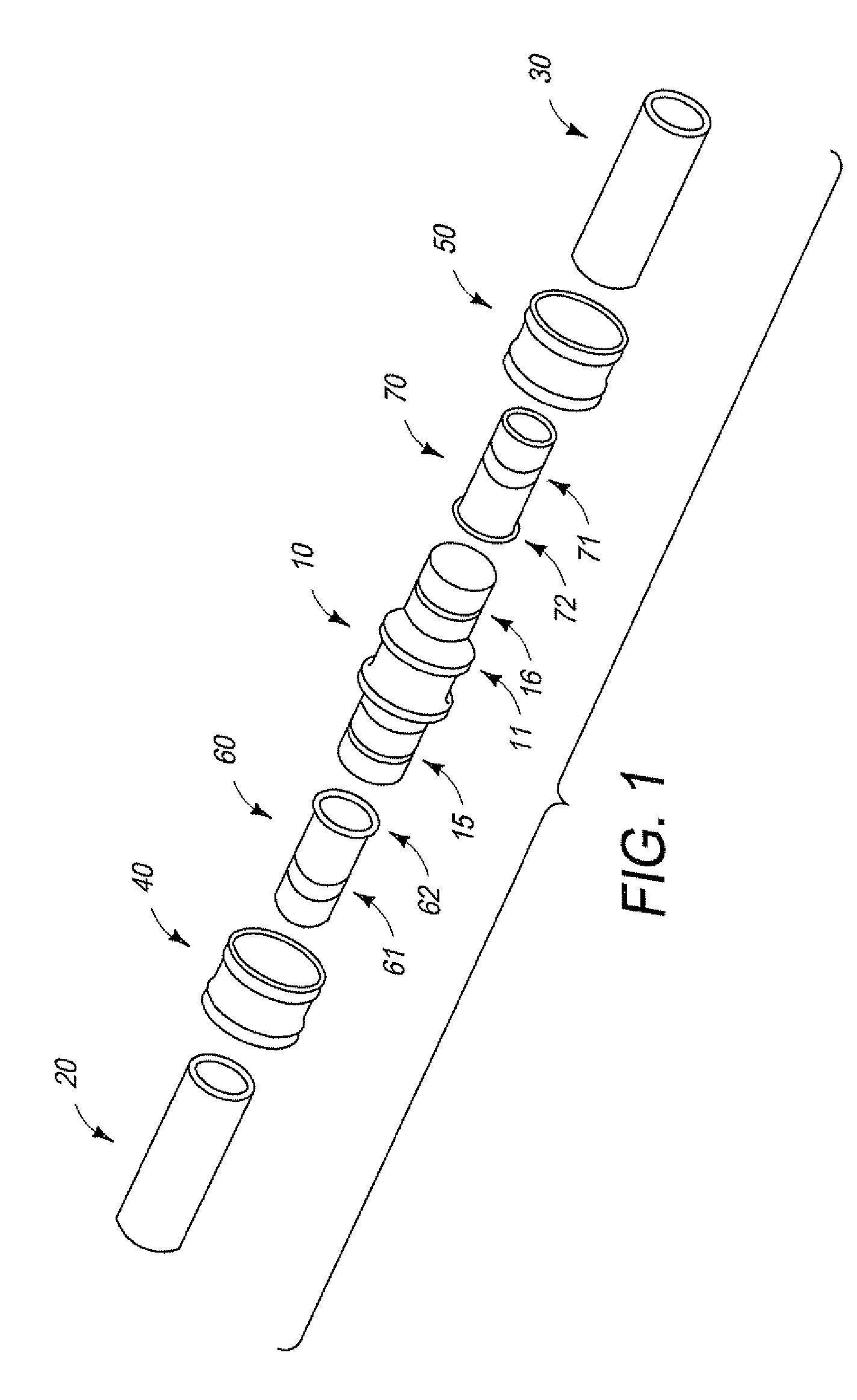
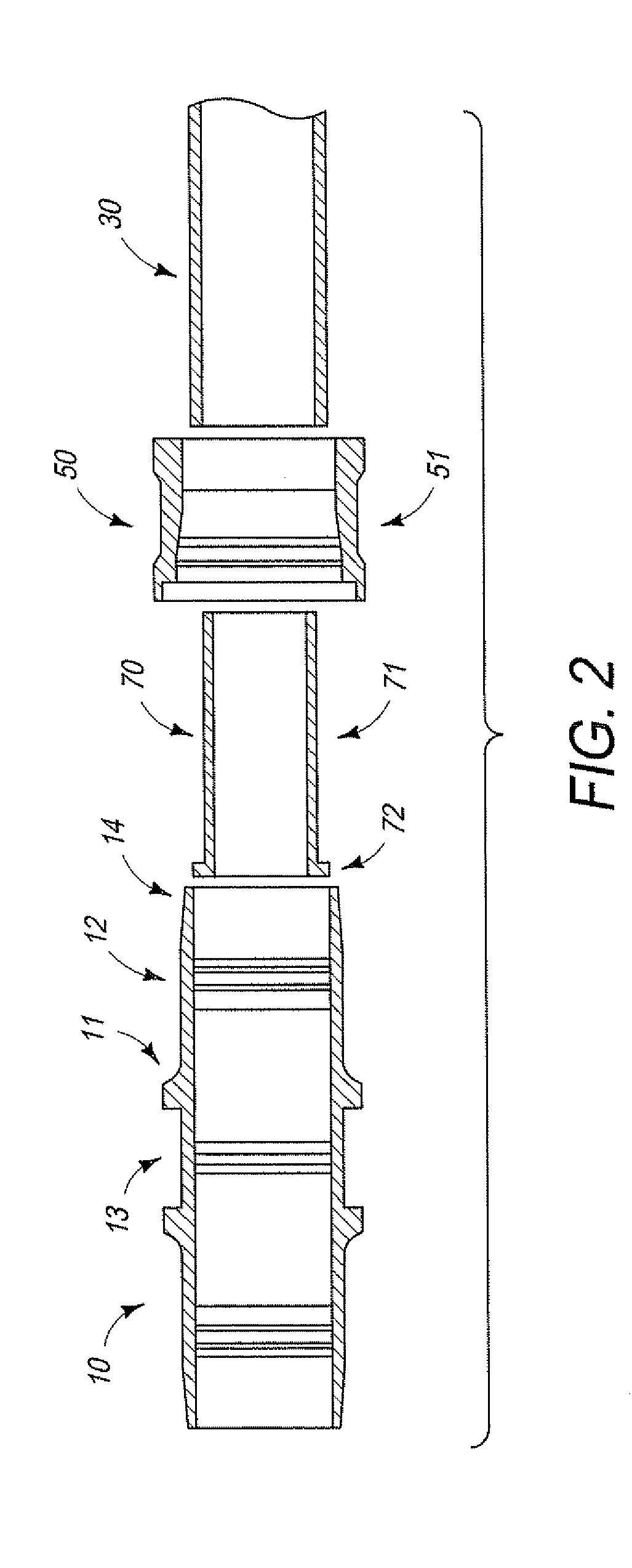
[0013]FIG. 1 illustrates a fluid fitting formed of a first sleeve 10 having a substantially cylindrical body and two open cylindrical ends for insertion of corresponding cylindrical second sleeves 60, 70 and tubes 20, 30. The outer surface of first sleeve 10 is adapted to accept a pair of swage rings 50, 60. An inner surface of first sleeve 10 defines an axial bore for receiving second sleeves 60, 70 and tubes 20, 30.

[0014]First sleeve 10 has a symmetrical configuration on opposite sides of a first or center portion 13 (FIGS. 2 and 3). Second sleeve 60 and tube 20 are received within first end 15 of sleeve 10. Likewise, second sleeve 70 and tube 30 are received within second end 16 of sleeve 10. Swage ring 40 slides over the exterior of first end 15 and includes a tapered inner surface that contacts and slides over tapered outer end surface 14 of sleeve 10. Likewise, swage ring 50 slides over the exterior of second end 16 and includes a tapered inner surface that contacts tapered ou...


PUM

PropertyMeasurementUnit
diameteraaaaaaaaaa
axial movementaaaaaaaaaa
heightaaaaaaaaaa

Abstract

A fluid fitting for attachment to a tube includes a cylindrical first sleeve having a tapered outer end surface and an inner surface defining an axial bore for receiving the tube. A cylindrical second sleeve creates an annular space for receiving the tube between the first and second sleeves when the second sleeve is placed within the axial bore. The axial bore has substantially equal diameter throughout. A swage ring has a tapered inner surface that axially swages the swage ring to the first sleeve, second sleeve and tube. A first sleeve shoulder restricts axial movement of the swage ring. A first portion protrudes from the inner surface of the first sleeve to restrict axial movement of the second sleeve.

Description

BACKGROUND OF THE INVENTION[0001]1. Field of the Invention[0002]This invention relates to a fluid fitting for soft tubing with high temperature capabilities.[0003]2. Description of Related Art[0004]Swaged fittings are commonly used to connect tubes and pipes to each other in areas of fluid systems where a secure connection is critical, such as oxygen or other fluid systems in the aircraft, marine, petroleum and chemical industries. Connected tubes that convey fuel or hydraulic control fluids in an aircraft, for example, must withstand vibration and other adverse conditions without failure. Conventionally, the ends of a tube are inserted into a fitting, usually in the form of a cylindrical sleeve, and the fitting is then swaged with a swaging tool to produce a fluid-tight connection between the tubes. Fittings are commonly used to connect metal tubes to each other in a variety of applications, such as in the aerospace industry to convey fuel, hydraulic control fluids and the like. Co...

Claims


Application Information

Patent Timeline
Patent Type & Authority Patents(United States)
IPC IPC(8): F16L13/14
CPCF16L33/2076Y10T29/49913
Inventor DANHASH, MAY
Owner DESIGNED METAL CONNECTIONS
Why Eureka
Try Eureka