3D pointing device and method for compensating rotations of the 3D pointing device thereof

a pointing device and 3d technology, applied in the field of 3d pointing devices, can solve the problems that the pointing device and compensation disclosed therein cannot accurately or properly calculate or obtain the movements, angles and directions of the pointing device, and the zsub>d /sub>may be greatly affected and erred, and may only be able to output the known prior ar

Active Publication Date: 2013-10-08
CYWEE GROUP
View PDF9 Cites 6 Cited by
  • Summary
  • Abstract
  • Description
  • Claims
  • Application Information

AI Technical Summary

Benefits of technology

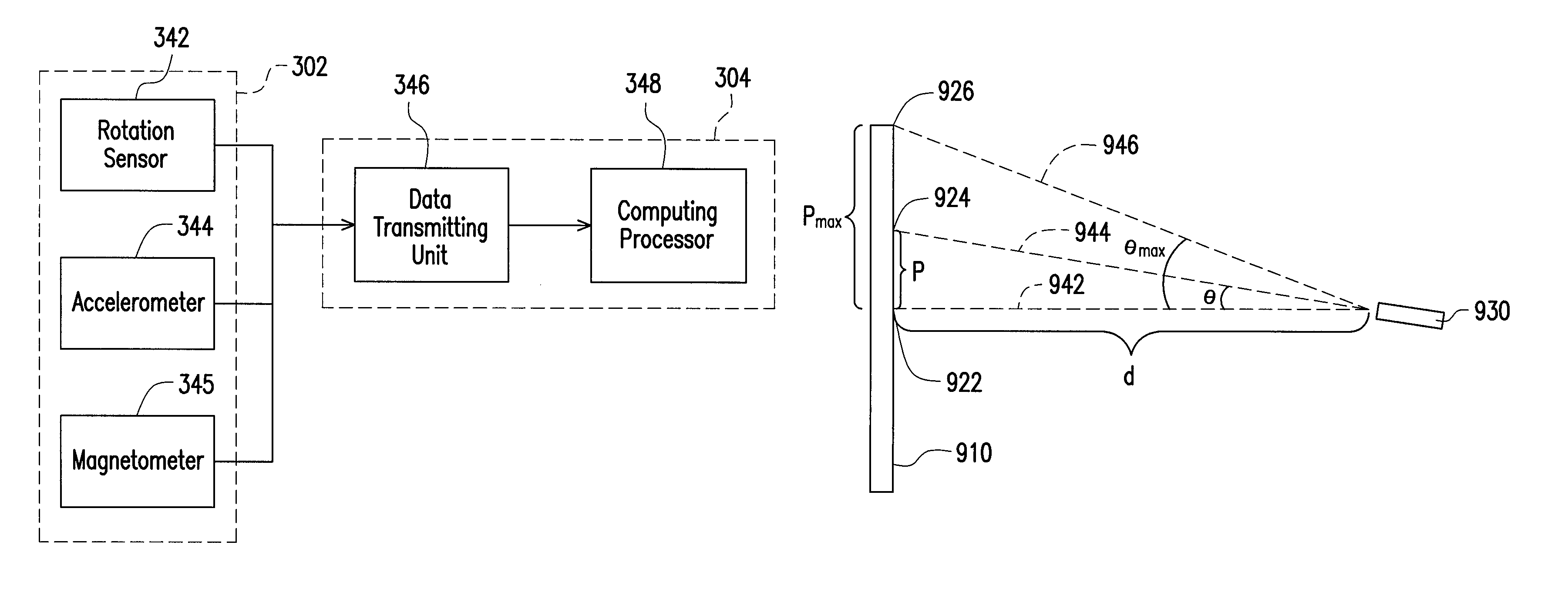
[0011]According to one aspect of an exemplary embodiment of the present invention, an electronic device utilizing a nine-axis motion sensor module for use in for example computers, motion detection or navigation is provided. The electronic device comprises an 
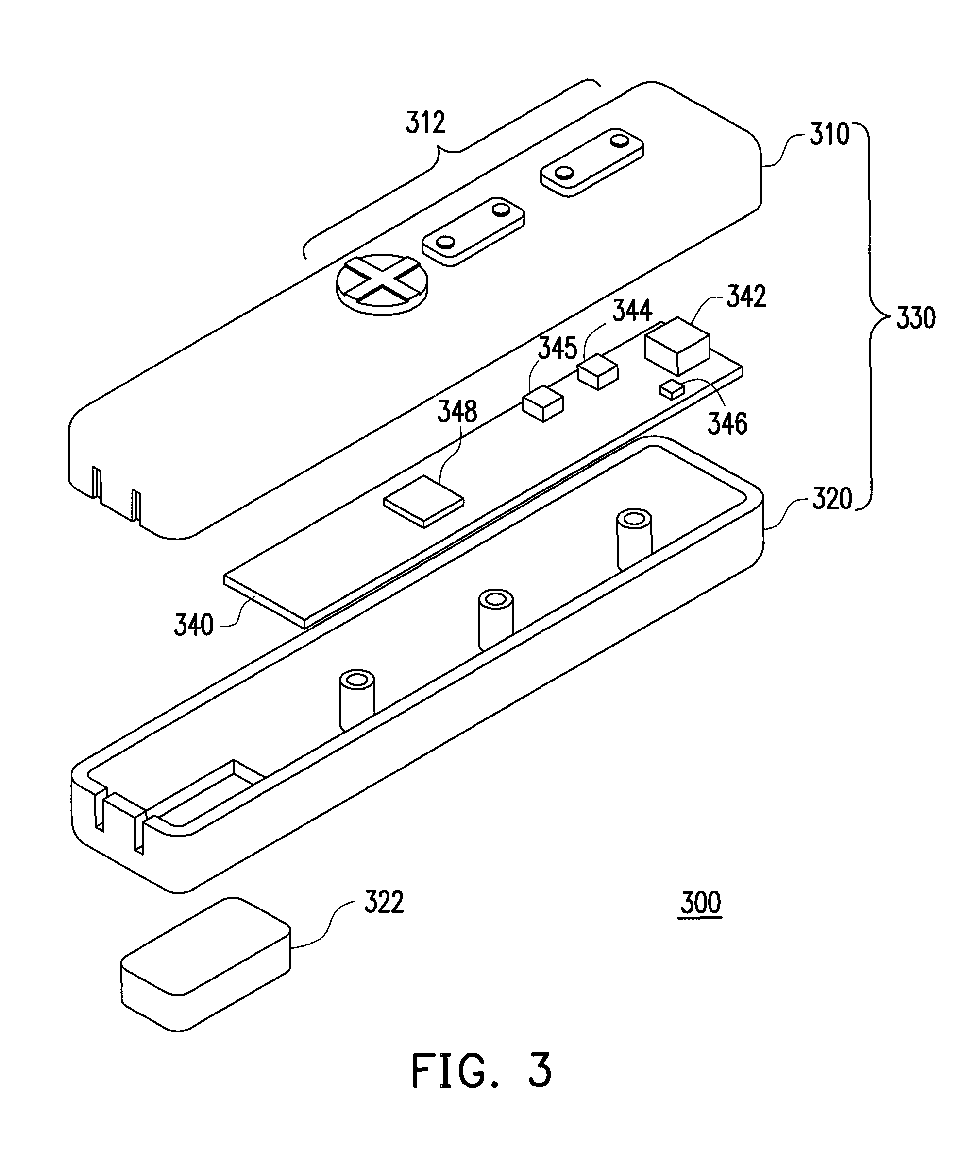
accelerometer to measure or detect axial accelerations Ax, Ay, Az, a magnetometer to measure or detect magnetism Mx, My, Mz and a rotation sensor to measure or detect angular velocities ωx, ωy, ωz such that resulting deviation including resultant angles comprising yaw, pitch and roll angles in a spatial pointer frame of the electronic device subject to movements and rotations in dynamic environments may be obtained and such that said resulting deviation including said resultant angles may be obtained and outputted in an absolute manner reflecting or associating with the actual movements and rotations of the electronic device of the present invention in said spatial pointer reference frame and preferably excluding undesirable external interferences in the dynamic environments.
[0012]According to another aspect of the present invention, the present invention provides an enhanced comparison method and / or model to eliminate the accumulated errors as well as noises over time associated with signals generated by a combination of motion sensors, including the ones generated by accelerometers Ax, Ay, Az, the ones generated by magnetometers Mx, My, Mz and the ones generated by gyroscopes ωx, ωy, ωx in dynamic environments. In other words, accumulated errors associated with a fusion of signals from a motions sensor module comprising a plurality of motion sensors to detect movements on and rotations about different axes of a reference frame may be eliminated or corrected.
[0013]According to still another aspect of the present invention, the present invention provides an enhanced comparison method to correctly calculating and outputting a resulting deviation comprising a set of resultant angles including yaw, pitch and roll angles in a spatial pointer frame, preferably about each of three orthogonal coordinate axes of the spatial pointer reference frame, by comparing signals of rotation sensor related to angular velocities or rates with the ones of accelerometer related to axial accelerations and the ones of magnetometer related to magnetism such that these angles may be accurately outputted and obtained, which may too be further mapping to another reference frame different from said spatial pointer frame.
[0014]In the event of interferences including external interferences introduced by either the device user or the surrounding environment, such as external electromagnetic fields, according to still another aspect of the present invention, the present invention provides a unique update program comprising a data association model to intelligently process signals received from a motion sensor module to output a resultant deviation preferably in 3D reference frame such that the adverse effects caused by the interferences may be advantageously reduced or compensated.
[0016]According to another example embodiment of the present invention, an electronic device capable of generating 3D deviation angles and for use in for example computers, 
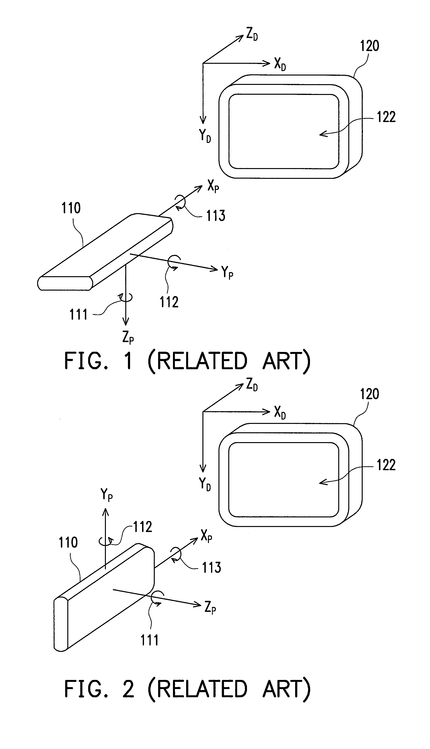
motion detection or navigation is provided. The electronic device may utilize a nine-axis motion sensor module with an enhanced comparison method or model for eliminating accumulated errors of said nine-axis motion sensor module to obtain deviation angles corresponding to movements and rotations of said electronic device in a spatial pointer reference frame. The comparison method or model may be advantageously provided by comparing signals from the abovementioned nine-axis motion sensor module capable of detecting rotation rates or angular velocities of the electronic device about all of the XP, YP and ZP axes as well as axial accelerations and ambient magnetism including such as Earth's magnetic field or that of other planets of the electronic device along all of the XP, YP and ZP axes such that deviation angles of the resultant deviation of the electronic device of the present invention may be preferably obtained or outputted in an absolute manner. In other words, the present invention is capable of accurately outputting the abovementioned deviation angles including yaw, pitch and roll angles in a 3D spatial pointer reference frame of the 3D pointing device to eliminate or reduce accumulated errors and noises generated over time in a dynamic environment including conditions such as being subject to a combination of continuous movements, rotations, external gravity forces, magnetic field and additional extra accelerations in multiple directions or movement and rotations that are continuously nonlinear with respect to time; and furthermore, based on the deviation angles being compensated and accurately outputted in 3D spatial reference frame may be further mapped onto or translated into another reference frame such as the abovementioned display frame, for example a reference in two-dimension (2D).
[0018]According to another example embodiment of the present invention, a method for compensating accumulated errors of signals of the abovementioned nine-axis motion sensor module in dynamic environments associated in a spatial reference frame is provided. In one embodiment, the method may be performed or handled by a hardware processor. The processor is capable of compensating the accumulated errors associated with the resultant deviation in relation to the signals of the abovementioned nine-axis motion sensor module of the 3D pointing device subject to movements and rotations in a spatial reference frame and in a dynamic environment by performing a data comparison to compare signals of rotation sensor related to angular velocities with the ones of accelerometer related to axial accelerations and the ones of magnetometer related to magnetism such that the resultant deviation corresponding to the movements and rotations of the 3D pointing device in the 3D spatial reference frame may be obtained accurately over time in the dynamic environments.

Problems solved by technology

The pointing device by Liberty utilizing a 5-axis motion sensor may not output deviation angles of the pointing device in, for example, a 3D reference frame; in other words, due to due to the limitation of the 5-axis motion sensor of accelerometers and gyro-sensors utilized therein, the pointing device by Liberty cannot output deviation angles readily in 3D reference frame but rather a 2D reference frame only and the output of such device having 5-axis motion sensors is a planar pattern in 2D reference frame only.
In addition, it has been found that the pointing device and compensation disclosed therein cannot accurately or properly calculate or obtain movements, angles and directions of the pointing device while being subject to undesirable interferences, external or internal, in the dynamic environment during the obtaining of the signals generated by the motion sensors, in particular, during unexpected drifting movements and / or accelerations along with the direction of gravity.
In other words, it has been found that dynamic actions or extra accelerations including additional accelerations, in particular the one acted upon the direction substantially parallel to or along with the gravity imposed on the pointing device with the compensation methods provided by Liberty, said pointing device by Liberty cannot properly or accurately output the actual yaw, pitch and roll angles in the spatial reference frame XPYPZP and following which, consequently, the mapping of the spatial angles onto any 2D display reference frame such as XDYDZD may be greatly affected and erred.
Furthermore, the reading of the accelerometer may be accurate only when the pointing device is static since due to the limitation on known accelerometers that these sensors may not distinguish the gravitational acceleration from the acceleration of the forces including centrifugal forces or other types of additional accelerations imposed or exerted by the user.
Furthermore, it has been found that known prior arts may only be able to output a “relative” movement pattern in a 2D reference frame based on the result calculated from the signals of motion sensors.
Such relative movement from the previous location to the next location with respect to time cannot accurately determine and / or output the next location, particularly in situations where the previous location may have been an erred location or have been faultily determined as an incorrect reference point for the next location that is to be calculated therefrom and obtained based on their relative relationship adapted.

Method used


Image

  • 3D pointing device and method for compensating rotations of the 3D pointing device thereof
  • 3D pointing device and method for compensating rotations of the 3D pointing device thereof
  • 3D pointing device and method for compensating rotations of the 3D pointing device thereof

Examples


Embodiment Construction

[0039]Detailed descriptions of preferred embodiments of the present invention recited herein are provided for illustrative purposes only; examples of which are too illustrated in the accompanying drawings. In addition, similar reference numbers in the drawings and the description may too refer to similar parts or components.

[0040]FIG. 3 is an exploded diagram showing an electronic device 300 according to one embodiment of the present invention, such as a pointing device. The electronic device 300 is subject to movements and rotations in dynamic environments in a spatial reference frame such as a 3D reference frame. The spatial reference frame is analogous to the reference frame XPYPZP also shown in FIG. 1 and FIG. 2. The movements and rotations of the electronic device 300, such as a pointing device, in the aforementioned dynamic environments in the spatial reference frame may be continuously nonlinear with respect to time. The term of “dynamic” recited herein may refer to moving or...


PUM


Abstract

A 3D pointing device utilizing an orientation sensor, capable of accurately transforming rotations and movements of the 3D pointing device into a movement pattern in the display plane of a display device is provided. The 3D pointing device includes the orientation sensor, a rotation sensor, and a computing processor. The orientation sensor generates an orientation output associated with the orientation of the 3D pointing device associated with three coordinate axes of a global reference frame associated with the Earth. The rotation sensor generates a rotation output associated with the rotation of the 3D pointing device associated with three coordinate axes of a spatial reference frame associated with the 3D pointing device itself The computing processor uses the orientation output and the rotation output to generate a transformed output associated with a fixed reference frame associated with the display device above. The transformed output represents a segment of the movement pattern.

Description

CROSS-REFERENCE TO RELATED APPLICATION[0001]This application is a continuation in part application of and claims the priority benefit of U.S. application Ser. No. 13 / 072,794, filed on Mar. 28, 2011, now pending. The prior application Ser. No. 13 / 072,794 is a continuation in part application of and claims the priority benefit of U.S. application Ser. No. 12 / 943,934, filed on Nov. 11, 2010, now pending, which claims the priority benefit of U.S. provisional application Ser. No. 61 / 292,558, filed on Jan. 6, 2010. The entirety of each of the above-mentioned patent applications is hereby incorporated by reference herein and made a part of this specification.BACKGROUND OF THE INVENTION[0002]1. Field of the Invention[0003]The present invention generally relates to a 3D pointing device, more particularly to a 3D pointing device for use in computers, motion detection or navigation utilizing a orientation sensor and a method for compensating signals of the orientation sensor subject to movemen...

Claims


Application Information

Patent Timeline
Patent Type & Authority Patents(United States)
IPC IPC(8): G06F3/033G09G5/08
CPCG06F3/0346
Inventor YE, ZHOULI, CHIN-LUNGLIOU, SHUN-NAN
Owner CYWEE GROUP
Why Eureka
Try Eureka