
Method for controlling the position of a movable object, a control system for controlling a positioning device, and a lithographic apparatus

a technology of positioning device and movable object, which is applied in the direction of programme control, automatic controller, printer, etc., can solve the problems of general undesirable heat dissipation, relatively large amount of heat dissipation, and low efficiency of lorentz motors, so as to avoid undesirable effects of using such motors

Active Publication Date: 2013-10-08
ASML HLDG NV
View PDF15 Cites 5 Cited by
  • Summary
  • Abstract
  • Description
  • Claims
  • Application Information

AI Technical Summary

Benefits of technology

[0009]It is desirable to provide an actuator arrangement and control for a movable object, in particular a short stroke module of a wafer stage or reticle stage, in which various types of motors can be used for actuation of the same movable object and in which undesirable effects of using such motors are avoided.
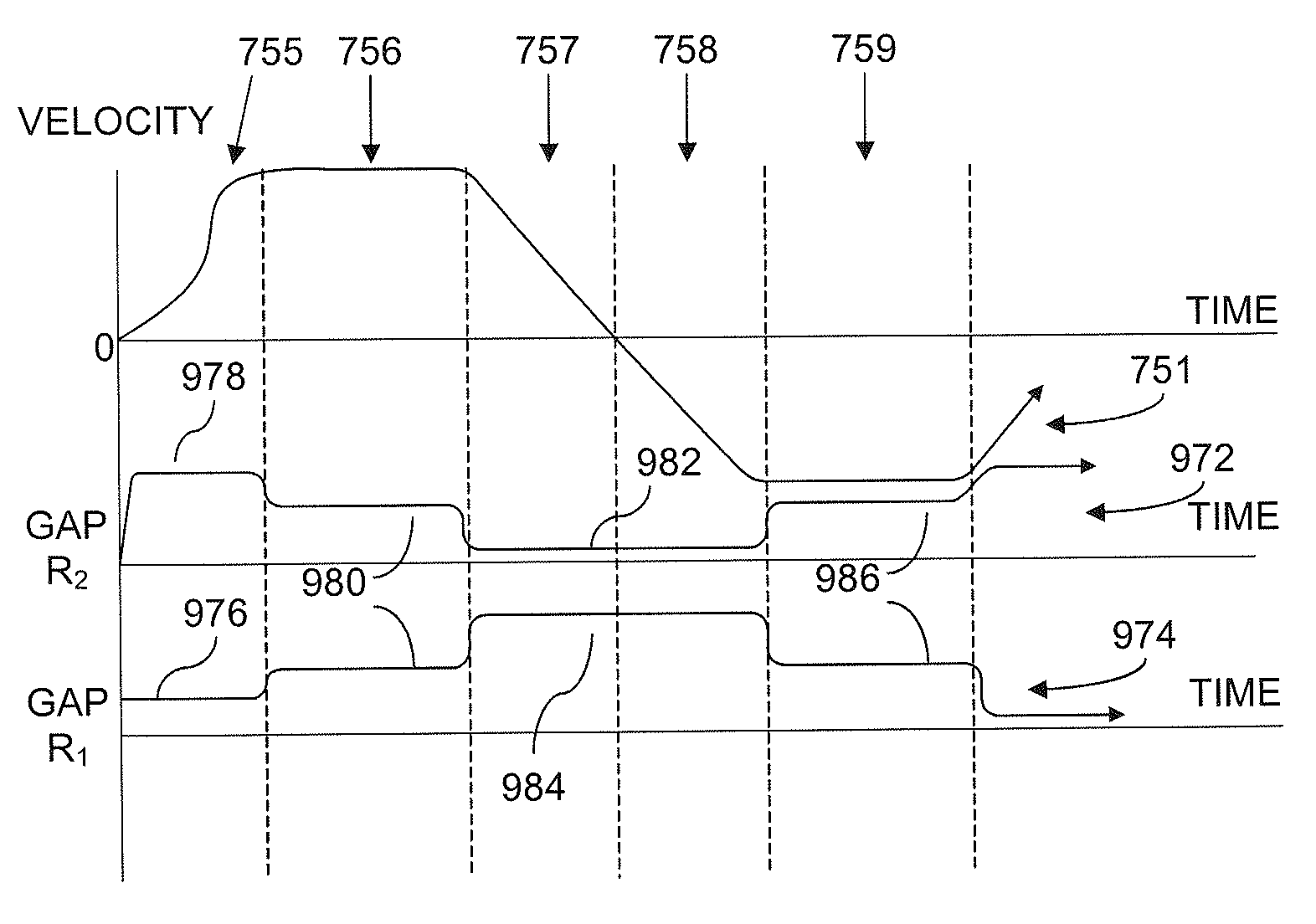
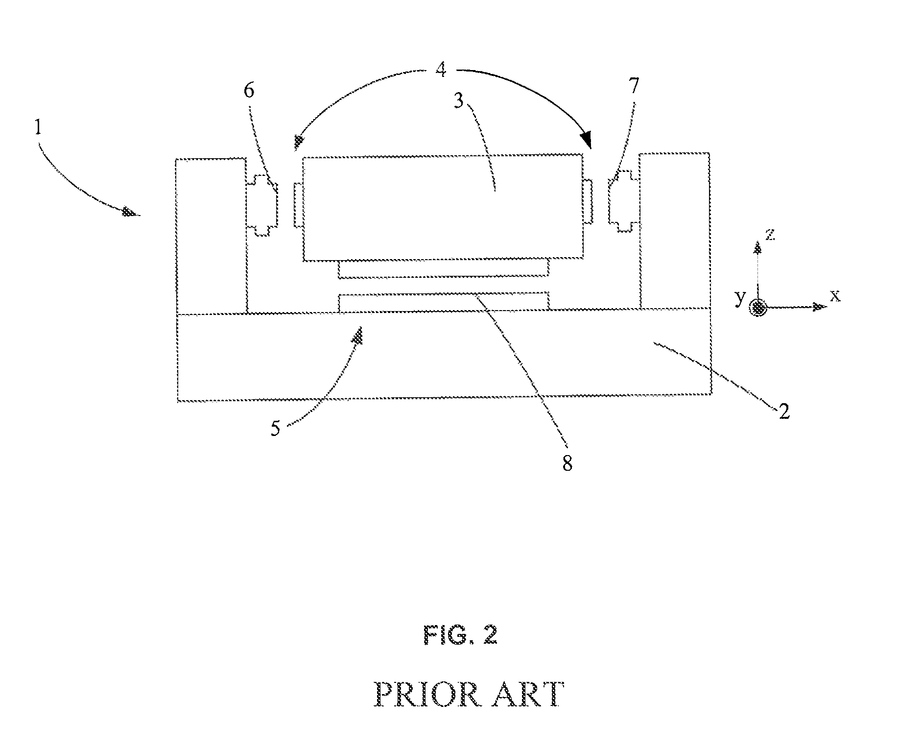
[0013]According to an embodiment, a method of positioning a short stroke stage of a lithographic apparatus in a first degree of freedom includes providing a motor assembly including one or more reluctance motors configured to accelerate the short stroke stage in the first degree of freedom. Each reluctance motor includes a core coupled to a long stroke stage associated with the short stroke stage, a flux carrier bar coupled to the short stroke stage, and a gap between the core and the flux carrier bar. The method further includes adjusting a size of the gap in accordance with respective movement events of the short stroke stage to minimize parasitic effects of a corresponding reluctance motor. In an embodiment, the adjusting the size of the gap includes adjusting the gap to a first size for high force acceleration of the short stroke stage in a first direction, adjusting the gap to a second size for constant velocity of the short stroke stage, and adjusting the gap to a third size for high force acceleration of the short stroke stage in a second direction.

Problems solved by technology

However, Lorentz motors are not highly efficient and a relatively large amount of heat is dissipated during the use of the motor.
Such dissipation of heat is generally undesirable, in particular when large forces have to be produced by the motor during acceleration of the short stroke module.
The generated heat may have a negative influence on the control accuracy of the Lorentz motor and on the performance of other systems in the lithographic apparatus.
It has been proposed to provide two types of motors for the actuator arrangement of the short stroke module, one type having a high efficiency but being relatively inaccurate, the other type being highly accurate, but having a low efficiency.
When the short stroke module is brought in the vicinity of the desired position, the control is taken over by a voice coil motor (a type of Lorentz motor that is highly accurate but has low efficiency), which is used to generate acceleration and deceleration forces to precisely control the position of the short stroke module.
However, the use of reluctance motors can behave nonlinearly and can also cause a parasitic damping effect.

Method used


Image

  • Method for controlling the position of a movable object, a control system for controlling a positioning device, and a lithographic apparatus
  • Method for controlling the position of a movable object, a control system for controlling a positioning device, and a lithographic apparatus
  • Method for controlling the position of a movable object, a control system for controlling a positioning device, and a lithographic apparatus

Examples


Embodiment Construction

[0037]Embodiments of the present invention are directed to positioning system control. This specification discloses one or more embodiments that incorporate the features of the present invention. The disclosed embodiment(s) merely exemplify the invention. The scope of the invention is not limited to the disclosed embodiment(s). The invention is defined by the claims appended hereto.

[0038]The embodiment(s) described, and references in the specification to “one embodiment,”“an embodiment,”“an example embodiment,” etc., indicate that the embodiment(s) described can include a particular feature, structure, or characteristic, but every embodiment can not necessarily include the particular feature, structure, or characteristic. Moreover, such phrases are not necessarily referring to the same embodiment. Further, when a particular feature, structure, or characteristic is described in connection with an embodiment, it is understood that it is within the knowledge of one skilled in the art t...


PUM


Abstract

A control system controls a positioning device displaceable in at least one degree of freedom by a reluctance motor. A force sensing element and a controller adjust force applied by the motor responsive to a force sensing element configured to sense force applied by the motor. The controller receives a signal representing force applied by the motor from the force sensing element, obtain an acceleration trajectory plan associated with a velocity trajectory plan for the positioning device, obtain a force trajectory plan associated with the acceleration trajectory plan, compare the force applied with a required amount of force obtained from the force trajectory, and adjust the amount of force applied by the motor based on the comparison. Related methods are also presented.

Description

CROSS-REFERENCE TO RELATED APPLICATIONS[0001]This application claims the benefit of U.S. Provisional Application No. 61,221,853, filed on Jun. 30, 2009 by ROUX, Stephen et al, the entire contents of which is incorporated herein by reference and for which priority is claimed under 35 U.S.C. §1.119(e).BACKGROUND[0002]1. Field of Invention[0003]This invention relates to a method for controlling the position of a movable object and a positioning system for a lithographic apparatus. More particularly, the invention relates to a method and a positioning system for controlling a short stroke module of a substrate stage or reticle stage of a lithographic apparatus.[0004]2. Related Art[0005]A lithographic apparatus is a machine that applies a desired pattern onto a substrate, usually onto a target portion of the substrate. A lithographic apparatus can be used, for example, in the manufacture of integrated circuits (ICs). In that instance, a patterning device, such as, for example, a mask or ...

Claims


Application Information

Patent Timeline
Patent Type & Authority Patents(United States)
IPC IPC(8): G03B27/58
CPCG05B19/416G05B2219/42083G03F7/70725G03F7/70758
Inventor ROUX, STEPHENCARTER, FREDERICK MICHAELMACKENZIE, ROSS IAN
Owner ASML HLDG NV
Learn More