
Power conversion circuits

a technology of power conversion circuit and power conversion circuit, which is applied in the direction of power conversion system, ac-dc conversion without reversal, electrical equipment, etc., can solve the problems of harmonic filter, a cost burden on a client, and the need for expensive and inefficient blocking reactors

Active Publication Date: 2013-10-08
THYCON PTY LTD
View PDF8 Cites 15 Cited by
  • Summary
  • Abstract
  • Description
  • Claims
  • Application Information

AI Technical Summary

Benefits of technology

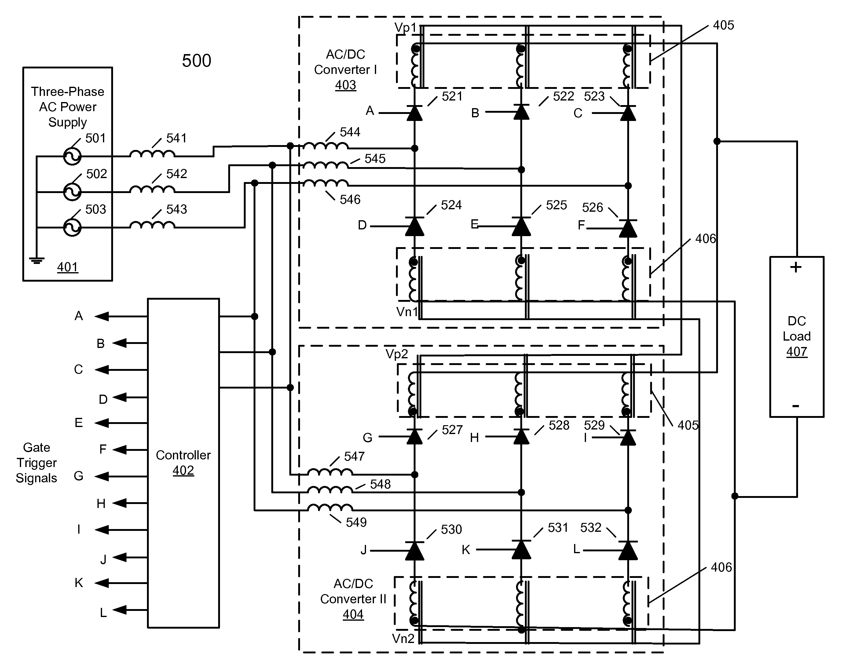
The patent is for an AC power system that includes two AC / DC converters and a controller. The first converter is connected to a DC load and a multi-phase AC power supply with multiple rectifiers. The second converter is connected in parallel with the first and has multiple rectifiers. The controller generates a triggering signal for each rectifier in both converters. The system can generate power cycles with the first converter's rectifier advanced to the second converter's rectifier's angle (in one cycle) and with the first converter's rectifier lagging in the second converter's cycle. The technical effect is an efficient and flexible power system that can generate high-quality AC power using multiple converters and controllers.

Problems solved by technology

Further, presence of harmonics in the AC supply can cause misoperation, misfiring or shutdown of sensitive equipment connected to the same AC bus, overvoltage due to harmonic resonance with passive components connected to the network, etc.
Also, expensive and inefficient blocking reactors may be required to avoid filter overloading by harmonics produced elsewhere in the plant or in the supply network.
Harmonic filters are also a cost burden that a client must pay in addition to the original purchase of electronic equipment in order to comply with standards.
However, phase shifting of the AC supply requires the use of one or more transformers.
This substantially increases the costs, operating losses, and equipment size and weight of converting equipment.
A typical three-phase transformer typically costs and weighs more than the AC / DC converter that is connected to it.
Despite the significant disadvantages associated with both of these methods, they remain the dominant techniques of alleviating harmonic distortion in AC power conversion systems.

Method used


Image

  • Power conversion circuits
  • Power conversion circuits
  • Power conversion circuits

Examples


Embodiment Construction

[0032]In the following description, numerous details are set forth to provide a more thorough explanation of embodiments of the present invention. It will be apparent, however, to one skilled in the art, that embodiments of the present invention may be practiced without these specific details. In other instances, well-known structures and devices are shown in block diagram form, rather than in detail, in order to avoid obscuring embodiments of the present invention.

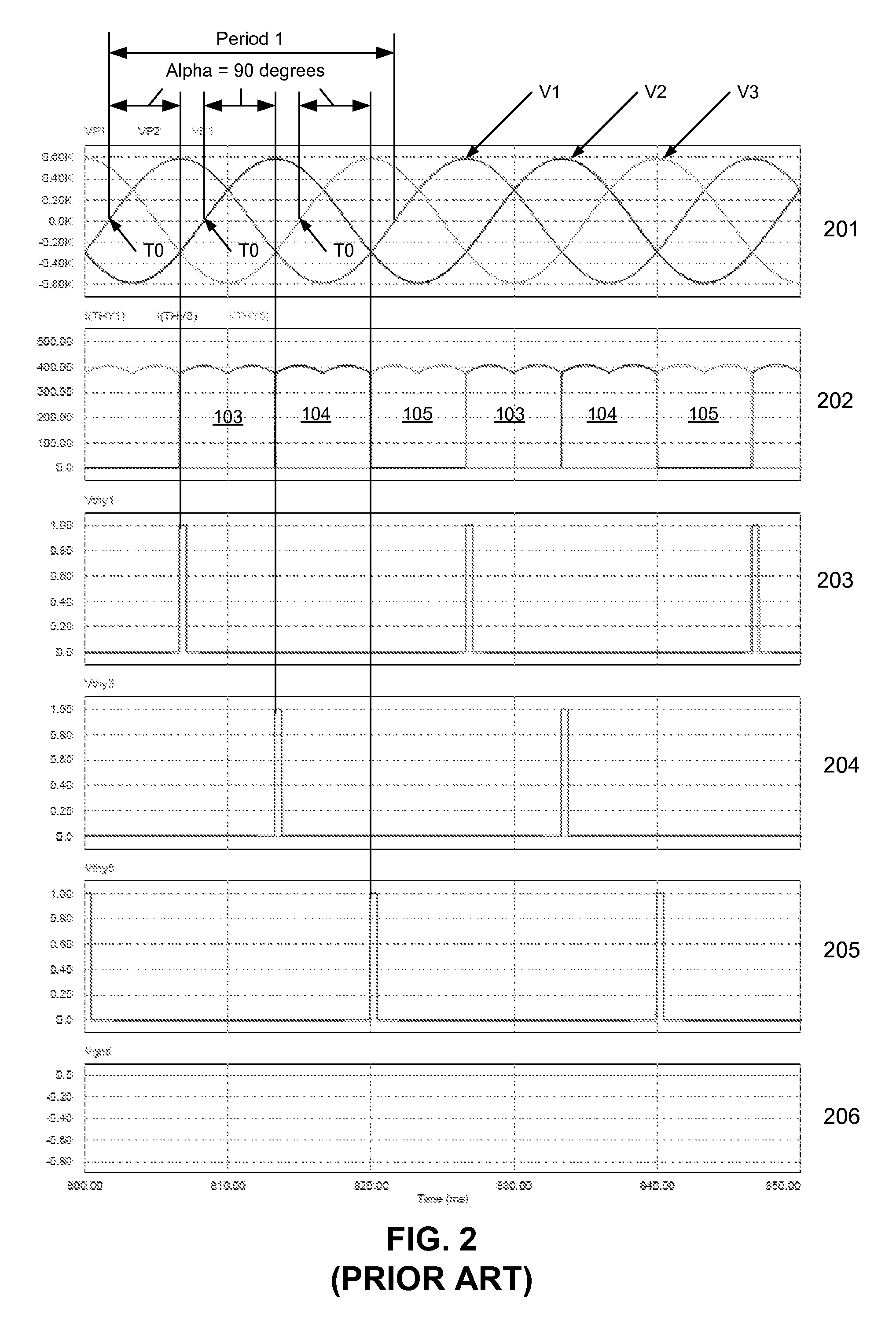
[0033]Reference in the specification to “one embodiment” or “an embodiment” means that a particular feature, structure, or characteristic described in connection with the embodiment is included in at least one embodiment of the invention. The appearances of the phrase “in one embodiment” in various places in the specification do not necessarily all refer to the same embodiment. Reference to a “power cycle”, also referred to as the period, refers to the time interval required for the AC supply voltage to complete one cycle...


PUM


Abstract

According to one embodiment, an AC power system includes a first AC / DC converter to be coupled to a direct current (DC) load and a multi-phase AC power supply. The system further includes a second AC / DC converter coupled in parallel with the first AC / DC converter via an interphase transformer to the DC load and the multi-phase AC power supply. The system further includes a controller coupled to the first and second AC / DC converters, where the controller is configured to generate a gate trigger signal for firing each of the rectifiers for the first and second AC / DC converters. During a first power cycle, a rectifier of the first AC / DC converter is fired at a firing angle advanced to a firing angle of a corresponding rectifier of the second DC / DC converter. During a second power cycle, the rectifier of the first AC / DC converter is fired at a firing angle lagging to a firing angle of the corresponding rectifier of the second AC / DC converter.

Description

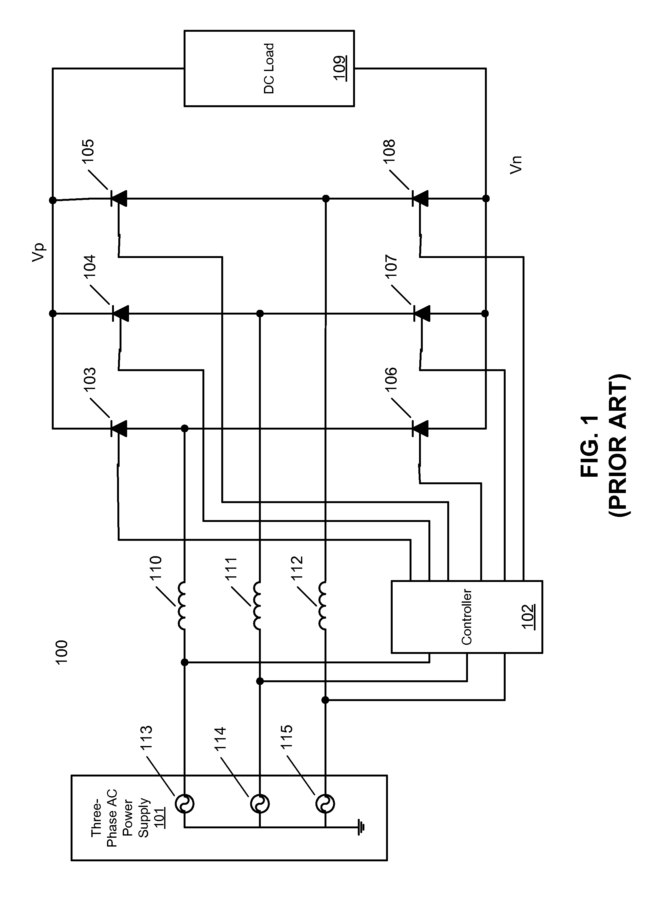
FIELD OF THE INVENTION[0001]The present invention relates generally to power conversion technologies. More particularly, this invention relates to power conversion circuits.BACKGROUND[0002]Conversion of three-phase power has found many industrial applications throughout this century. The proportion of converters connected to the supply grid has reached high levels in the industrialized world. In its simplest and most economical form, conversion of three-phase power is achieved by controlling the supply current in six steps per power supply cycle.[0003]FIG. 1 is a schematic diagram illustrating a typical six-pulse AC to DC converter. Referring to FIG. 1, a typical converter 100 includes a three-phase alternating current (AC) power supply 101 coupled to each of three inductors or alternate current (AC) reactors (or inductors) 110-112, each connected to a pair of rectifiers 103 and 106, 104 and 107, 105 and 108, respectively. Rectifiers 103-108 are controlled or switched on by a contro...

Claims


Application Information

Patent Timeline
IPC IPC(8): H02M7/155
CPCH02M1/12H02M7/17H02M7/10
Inventor NANUT, JAMESNANUT, PIA
Owner THYCON PTY LTD
Learn More