

Drain inlet vault and method of assembly
a technology of drain inlet vault and assembly method, which is applied in the direction of sewer cleaning, electric apparatus casing/cabinet/drawer, parking, etc., can solve the problem that my vault and assembly method are, however, susceptible to modification
- Summary
- Abstract
- Description
- Claims
- Application Information
AI Technical Summary
Benefits of technology
Problems solved by technology
Method used
Image

Examples
Embodiment Construction
.” The claims that follow define my vault and method of assembly, distinguishing them from the prior art; however, without limiting the scope of my vault and method of assembly as expressed by these claims, in general terms, some, but not necessarily all, of their features are:
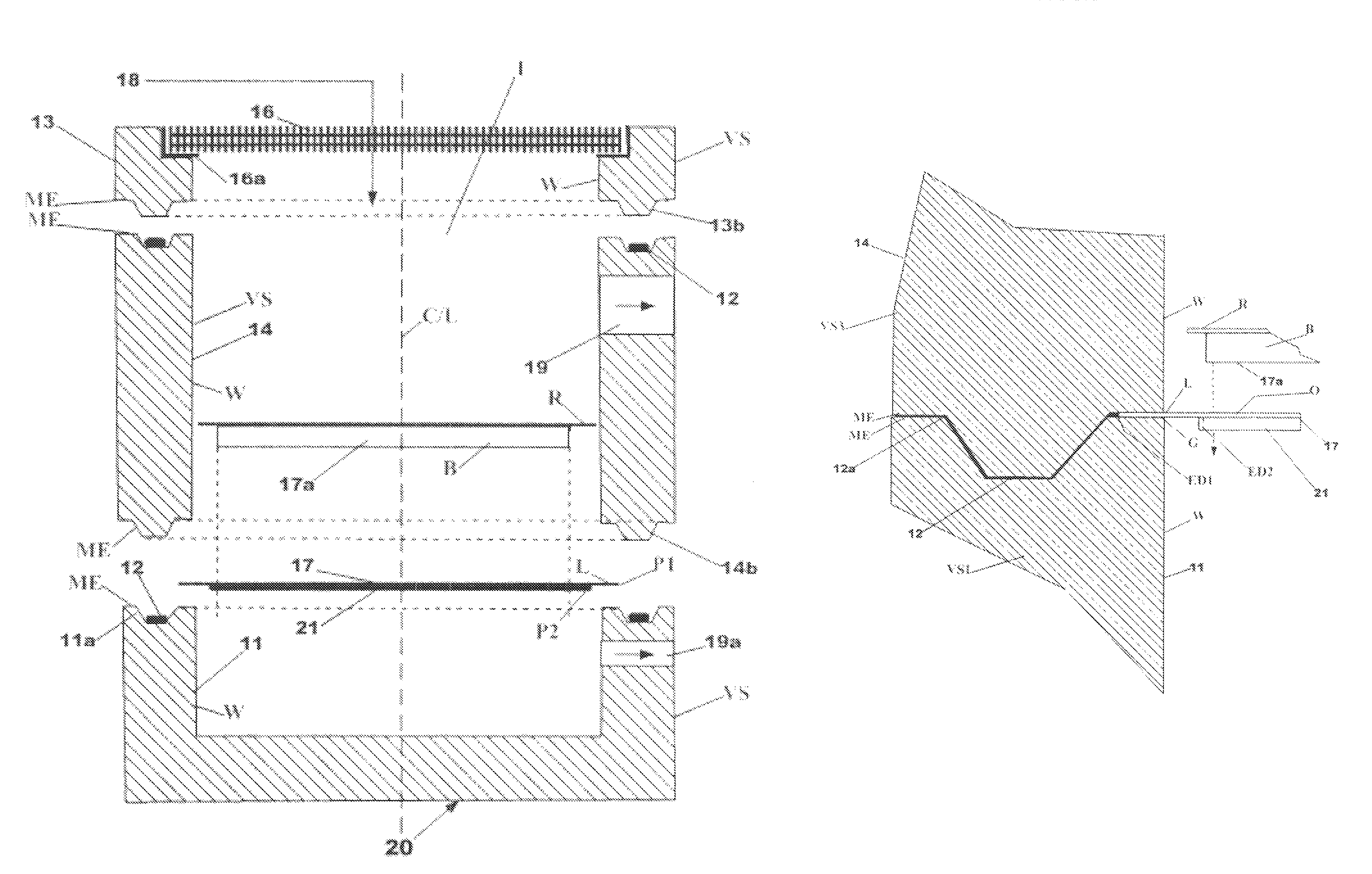
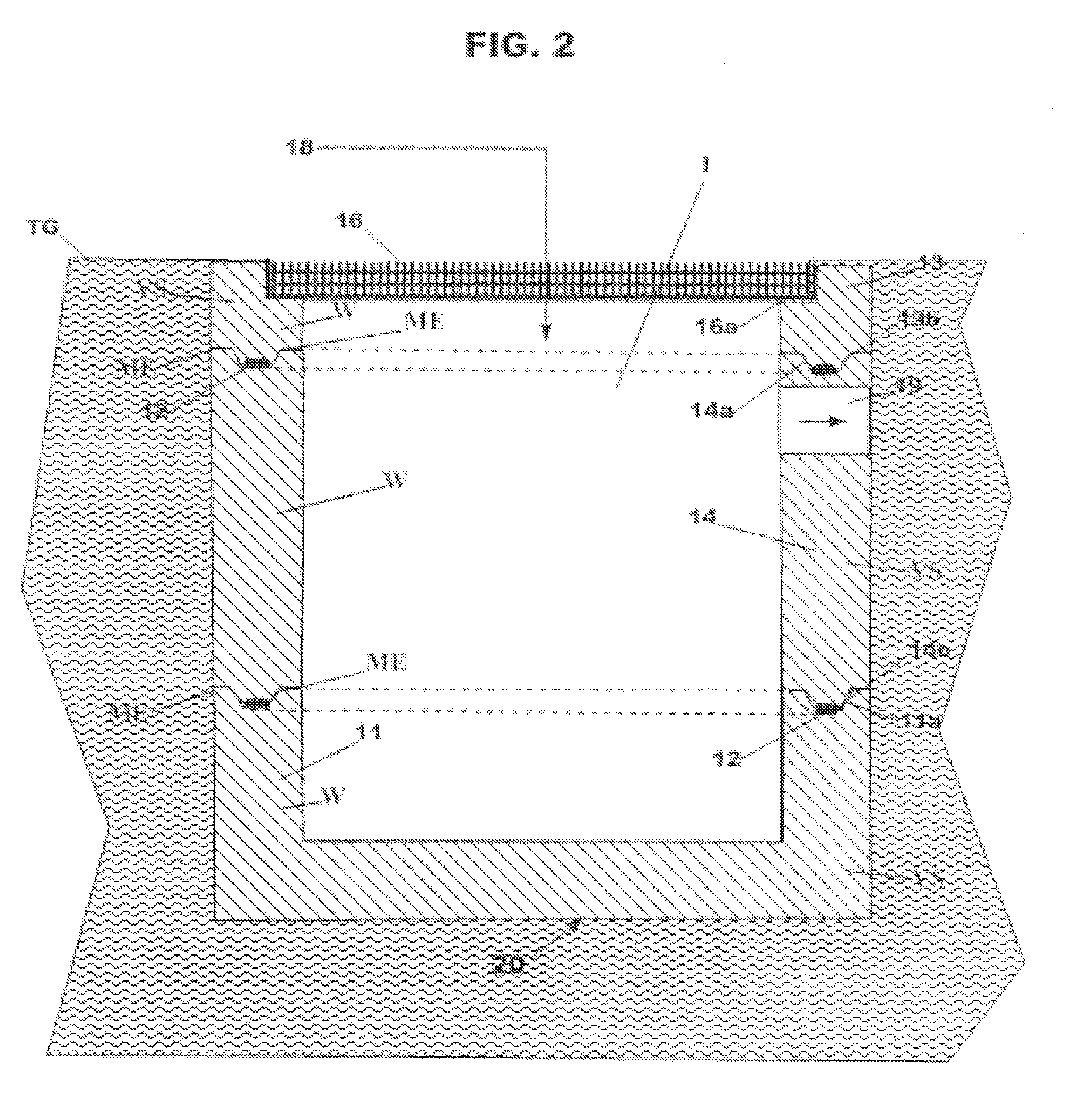
[0009]One, my drain inlet vault comprises a plurality of vault sections stacked together in substantial registration to form the vault. Two or more sections are employed and may include a base section and a cap section, but, as needed to achieve appropriate overall finished vault depth, one or more additional riser sections may be included. A sealant is between adjacent stacked together vault sections, and there is at least one support element for water treatment equipment, or a component thereof, positioned between at least one pair of adjacent stacked together vault sections. The sealant is placed between perimeter edges of adjacent stacked together vault sections prior to placing one section upon the other ...
PUM
 Abstract
Description
Claims
Application Information