Split sub-basement drill rig

a sub-basement, drill rig technology, applied in the direction of drilling pipes, rotary drilling, building scaffolds, etc., can solve the problems of requiring a relative complex series of pulleys, etc., to raise the rig floor, and achieve the effect of quick and easy raising

Active Publication Date: 2013-10-15
NAT OILWELL VARCO LP
View PDF49 Cites 34 Cited by
  • Summary
  • Abstract
  • Description
  • Claims
  • Application Information

AI Technical Summary

Benefits of technology

[0008]The present invention provides a sub-basement assembly for transportable, mobile drill rigs for supporting the drill rig floor. The assembly has a lower ‘stack’ height for transit but which can nonetheless be quickly and easily raised with a hydraulic cylinder as the substructure is erected. Although the height & size of the present invention's ‘floor’ is quite compact while in shipment, it provides for the full load carrying capacity and full size of conventional ‘floors’ during drilling operations. The linkage structure provides the ability for the rig floor to be raised with a hydraulic cylinder with the linkage then locked in place as part of the fig floor support structure.

Problems solved by technology

Very high tension loads are applied to the wire rope during assembly, and a relatively complex series of pulleys, etc. may be required to raise the rig floor.

Method used


Image

  • Split sub-basement drill rig
  • Split sub-basement drill rig
  • Split sub-basement drill rig

Examples


Embodiment Construction

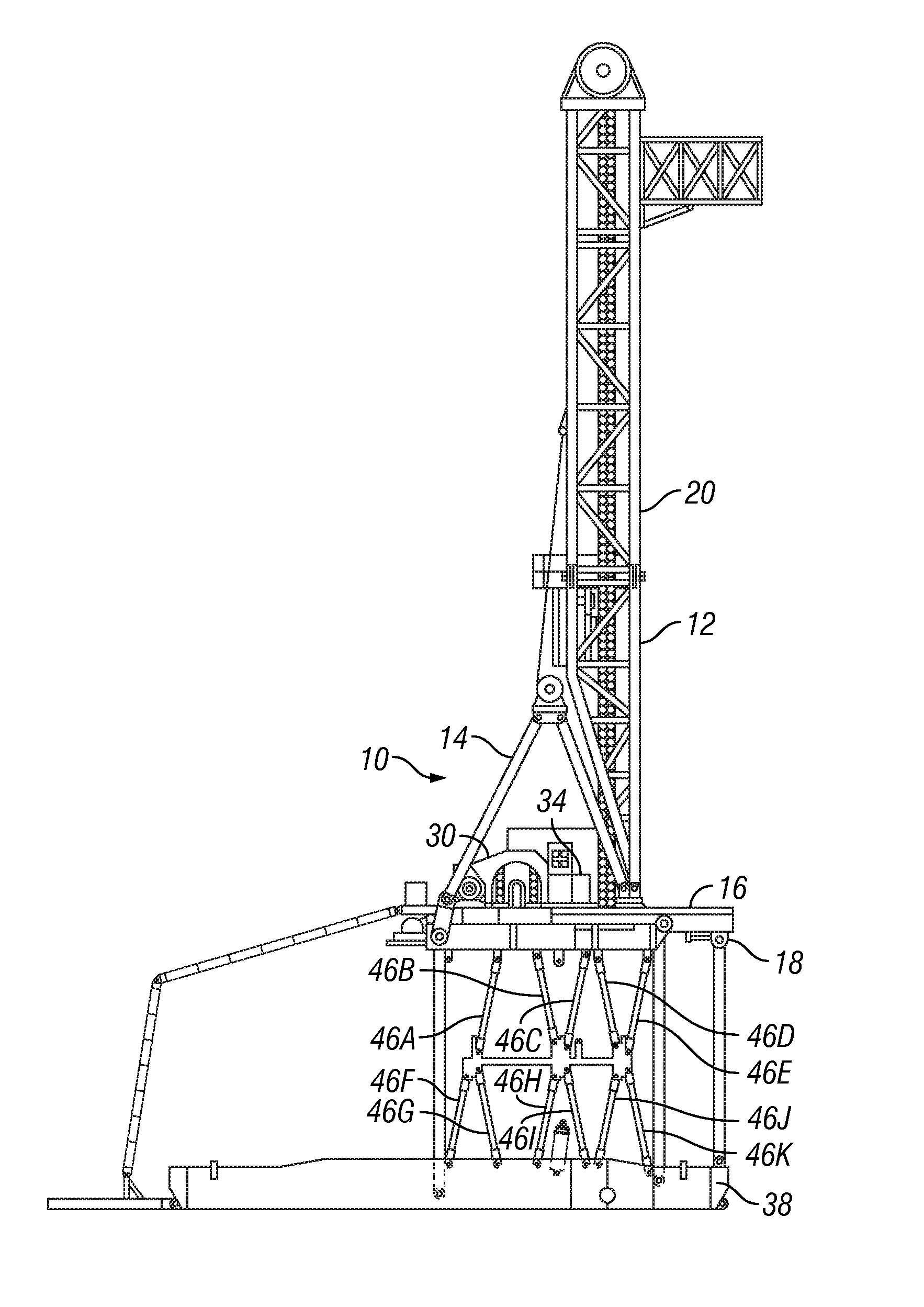
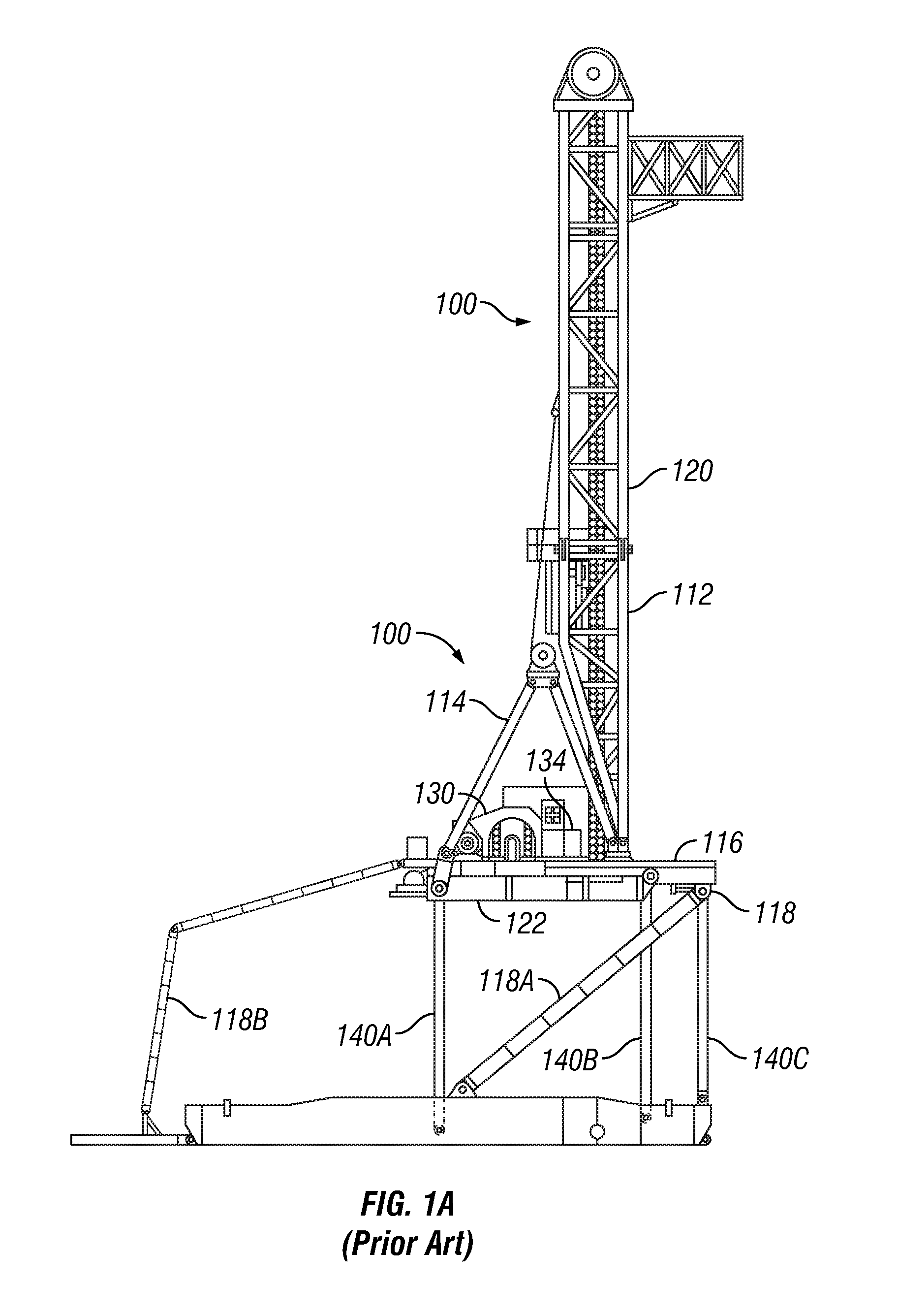
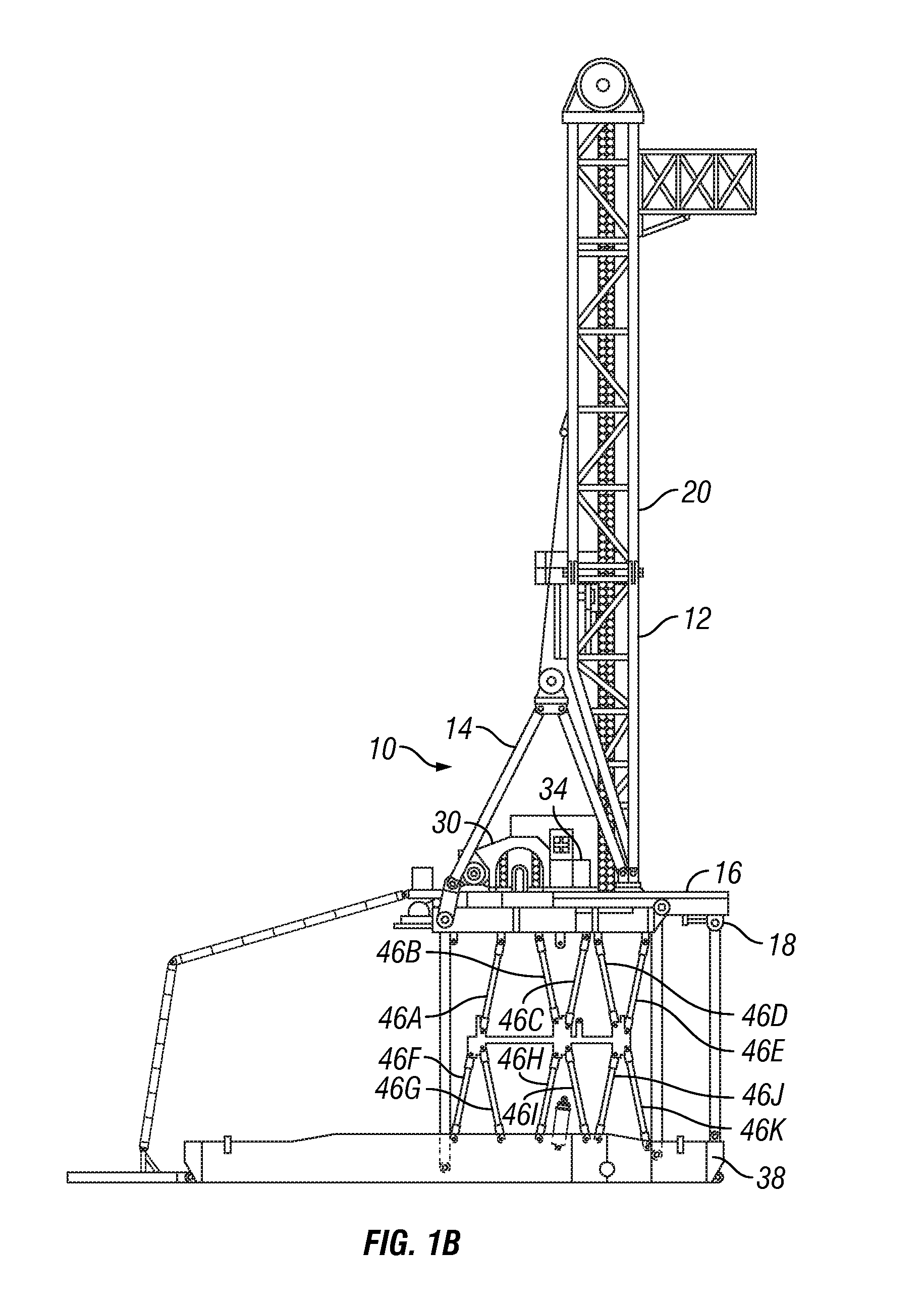
[0017]Referring now to FIG. 1B, the drill rig 10 of the present invention includes a mast assembly 20 and many other components for a transportable (i.e. portable) drill rig 100 known in the prior art, and therefore has many components in common with the present invention. The mast assembly 20 of the present invention includes a mast 12, an A-frame 14, as part of the rig 10, on a floor 16 mounted to a substructure 18. The mast 12 is pivotally connected to the floor 16. The mast 12 is a typical drilling rig mast with top sheaves (not shown). The rig floor 16 is supported upon the substructure 18 which is carried by the pivotable cross bracing links 46a, 46b, 46c, 46d, 46e, 46f, 46g, 46h, 46i, 46j, and 46k of the present invention. Other components of the rig 10 may include drawworks 30, a control system 34 and other machinery well known and commonly used in the industry.

[0018]The drill rig 10 is provided with a rig floor 16 elevating system which allows it to be raised from the shipp...


PUM


Abstract

A substructure of a drill rig includes, among other things, a base and an intermediate section that is adapted to be raised above the base, wherein the intermediate section is further adapted to be laterally moved in a first lateral direction relative to the base and maintained substantially parallel to the base during the raising of the intermediate section above the base. The substructure further includes a rig floor section that is adapted to be raised above the intermediate section, wherein the rig floor section is further adapted to be laterally moved in a second lateral direction relative to the base and maintained substantially parallel to the base during the raising of the rig floor section above the intermediate section, the second lateral direction being opposite to the first lateral direction.

Description

[0001]This application claims priority from U.S. provisional patent application Ser. No. 61 / 262,232, filed on Nov. 18, 2009, which is incorporated herein by reference.BACKGROUND OF THE INVENTION[0002]1. Field of the Invention[0003]This invention relates to road-transportable drill rigs for drilling boreholes into the earth to extract hydrocarbons, such as oil and natural gas, as well as other minerals.[0004]2. Description of the Related Art[0005]Drilling masts are the vertical structures used to support the drill string while a well is being drilled. Masts are usually rectangular in shape as opposed to the generally pyramidal shape of a derrick. The rectangular shape offers very good stiffness that allows the mast to be moved to a horizontal position for transport. Thus, drilling masts are very common on portable land rigs.[0006]FIG. 1A shows a mast assembly 120 for a transportable (i.e. portable) drill rig 100 of the prior art, but which has many components in common with the prese...

Claims


Application Information

Patent Timeline
Patent Type & Authority Patents(United States)
IPC IPC(8): E21B19/08E04H12/24E04G1/18
CPCE21B7/02
Inventor SOUCHEK, RICHARD DWAINE
Owner NAT OILWELL VARCO LP
Why Eureka
Try Eureka