Broadband clover leaf dipole panel antenna

a dipole panel antenna and clover leaf technology, applied in the field of directional radio frequency (rf) antenna radiators, can solve the problems of large power capacity, achieve broad bandwidth, eliminate cross-coupling, and eliminate mutual coupling

Inactive Publication Date: 2013-10-15
DIELECTRIC
View PDF5 Cites 4 Cited by
  • Summary
  • Abstract
  • Description
  • Claims
  • Application Information

AI Technical Summary

Benefits of technology

[0004]The foregoing antenna performance improvements are realized by embodiments of the present invention, which include an apparatus and method that provides a dual-input crossed dipole antenna that substantially eliminates mutual coupling between bays of a crossed dipole array, substantially eliminates cross-coupling between dipole elements within a single radiator, supports elliptical polarization, and realizes a broad bandwidth characterized by one or more frequency ranges over which the antenna exhibits a low standing wave ratio.

Problems solved by technology

Further, the above-described antenna designs have a large power capability and, more particularly, have a larger power capability than is typically required for applications to which these antennas are applied.

Method used


Image

  • Broadband clover leaf dipole panel antenna
  • Broadband clover leaf dipole panel antenna
  • Broadband clover leaf dipole panel antenna

Examples


Embodiment Construction

[0016]Generally speaking, embodiments of the present invention provide antennas that combine a plurality of crossed dipole radiators to substantially improve bandwidth in relatively low-power transmitting systems, e.g., a bandwidth enhancement is realized by combining at least two concentric rings in each loop element of the radiators included in the antennas.

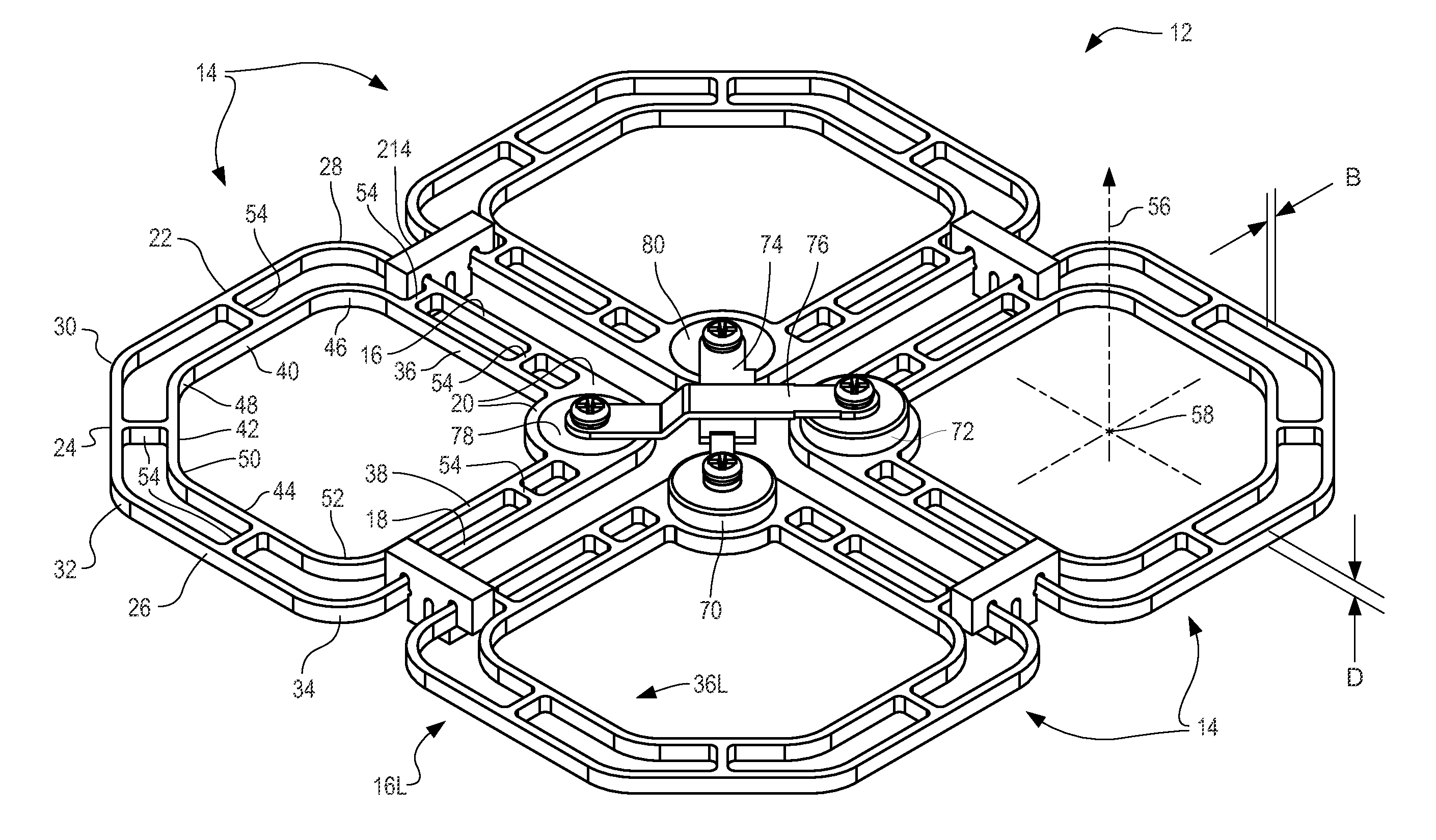
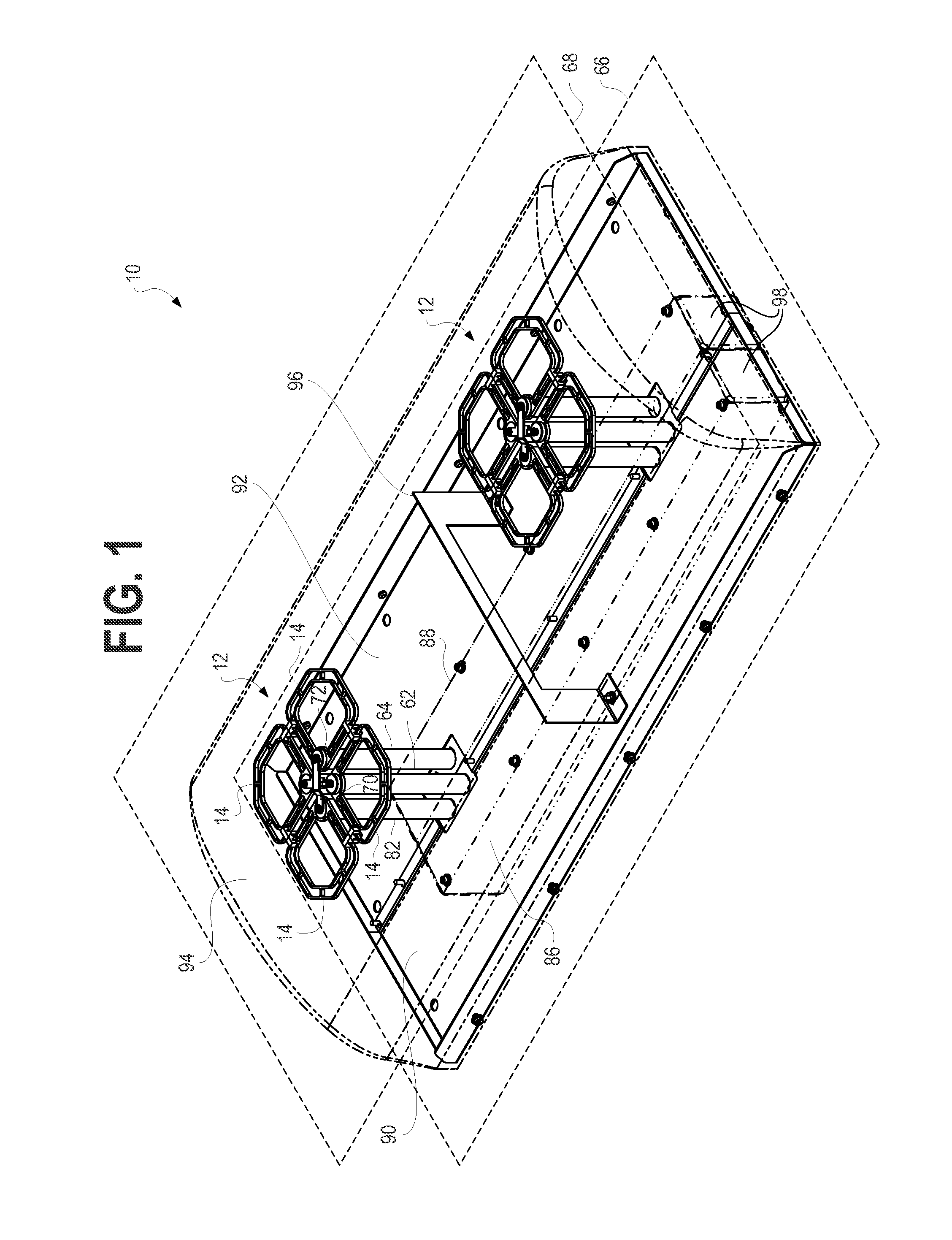
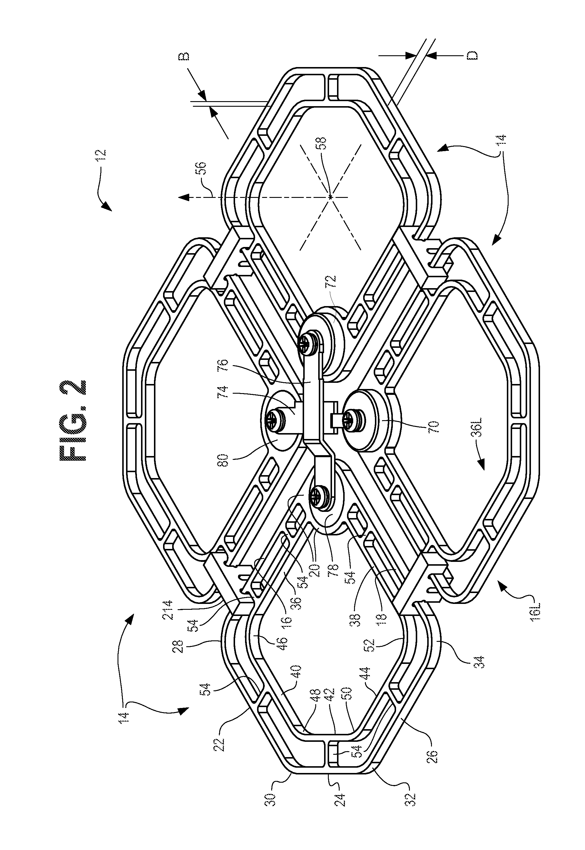
[0017]FIG. 1 shows an antenna 10 having at least one radiator 12. In one embodiment, the radiator 12 is dual-loop crossed dipole radiator 12. As will be described in greater detail below, a dipole is a device that emits and / or captures energy of an electromagnetic (EM) signal. More particularly, a dipole is a device having two similarly dimensioned, spatially separated, electrically isolated conductive parts. One of the two parts has an instantaneous energy state (from the EM signal) that is different from an instantaneous energy state of the other part. The two parts of a dipole may be referred to as monopoles. For purposes of...


PUM


Abstract

An antenna radiator is provided. The radiator includes four elements, each including a node, a first ring connected to the node, and a second ring connected to the node and disposed inside of and coplanar with the first ring. The first ring includes a first plurality of segments, and the second ring includes a second plurality of segments.

Description

FIELD OF THE INVENTION[0001]The present invention relates generally to electromagnetic signal antenna elements. More particularly, the present invention relates to directional radio frequency (RF) antenna radiators for low- to medium-power broadcasting, where the radiators are configurable to support single- or dual-feed and linear or elliptical, e.g., circular, polarization.BACKGROUND OF THE INVENTION[0002]In hybrid-coupled crossed-dipole radiators, balun-coupled loops, which are typically coplanar, convex, conductive, and substantially continuous, are arranged in a square layout. Each loop has two end-to-end connected, equal-length boundary segments including orthogonal and generally straight-sided portions. A signal feed point is located at a connection locus of the two segments. Diagonal pairs of the loops have a differential feed and constitute a dipole. Thus, two diagonal pairs of the loops form the square layout, which thereby form two crossed dipoles. Cross-coupling between ...

Claims


Application Information

Patent Timeline
Patent Type & Authority Patents(United States)
IPC IPC(8): H01Q21/26
CPCH01Q1/246H01Q9/28H01Q21/08H01Q21/26H01Q9/265H01Q19/108H01Q21/0081
Inventor LYTLE, GARY M.SCHADLER, JOHN L.KOKOTOFF, DAVID
Owner DIELECTRIC
Why Eureka
Try Eureka