Travel drive device for dump truck

a technology for traveling drive and dump trucks, which is applied in the direction of gearing details, gearing, transportation and packaging, etc., can solve the problems of lack of lubrication and insufficient strength of the spline-coupling portion, and achieve the effects of increasing the strength of the rotational load, enhancing the durability and the lifetime of the entire travel drive device, and enhancing the durability and reliability of the entire devi

Active Publication Date: 2013-10-22
NIHON KENKI CO LTD
View PDF10 Cites 10 Cited by
  • Summary
  • Abstract
  • Description
  • Claims
  • Application Information

AI Technical Summary

Benefits of technology

[0009]In view of the above-discussed problem with the conventional art, it is an object of the present invention to provide a travel drive device for a dump truck which can enhance the strength to a rotational load by providing a separate coupling member between an open end side of a spindle and a carrier to improve durability and lifetime of an entire device.
[0022]With this arrangement, the guide projection provided in the opposing surface portion of the cylindrical coupling member can beat off the lubricant oil ejected from the meshing part between the sun gear and each of the planetary gears toward the radial outside. The lubricating state can be maintained in the planetary gear bearing between the planetary gear and the support pin by guiding the beat lubricant oil in between each of the planetary gears and the support pin.

Problems solved by technology

However, this spline-coupling portion does not necessarily have sufficient strength in a case where a loading weight of the dump truck is increased to, for example, 250 tons or more, and a further improvement on the coupling portion is needed.
Therefore, it is difficult to supply a sufficient amount of the lubricant oil to a support pin and a planetary gear bearing rotatably (rotatably on its axis) supporting the planetary gear, creating a problem with possible occurrence of lubrication lack.

Method used


Image

  • Travel drive device for dump truck
  • Travel drive device for dump truck
  • Travel drive device for dump truck

Examples


first embodiment

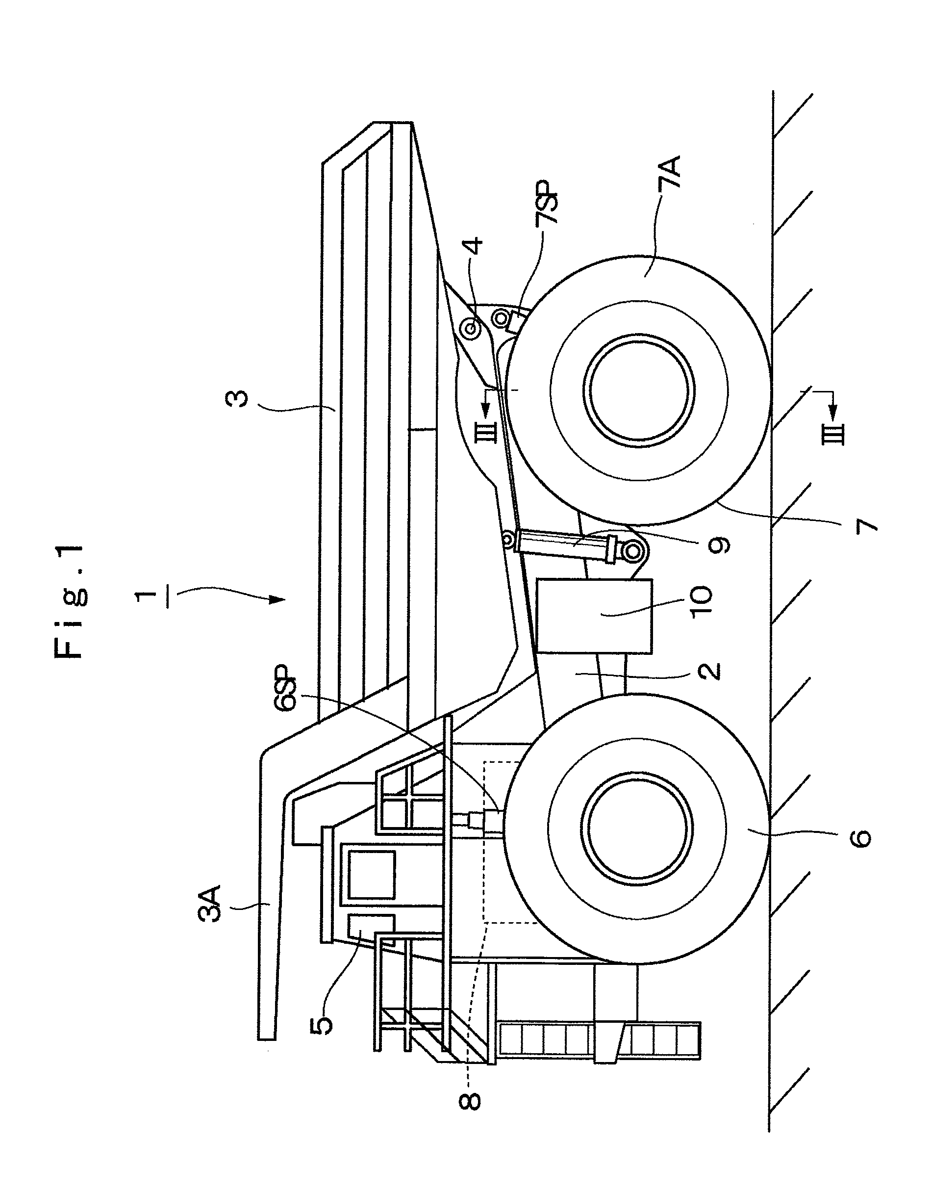
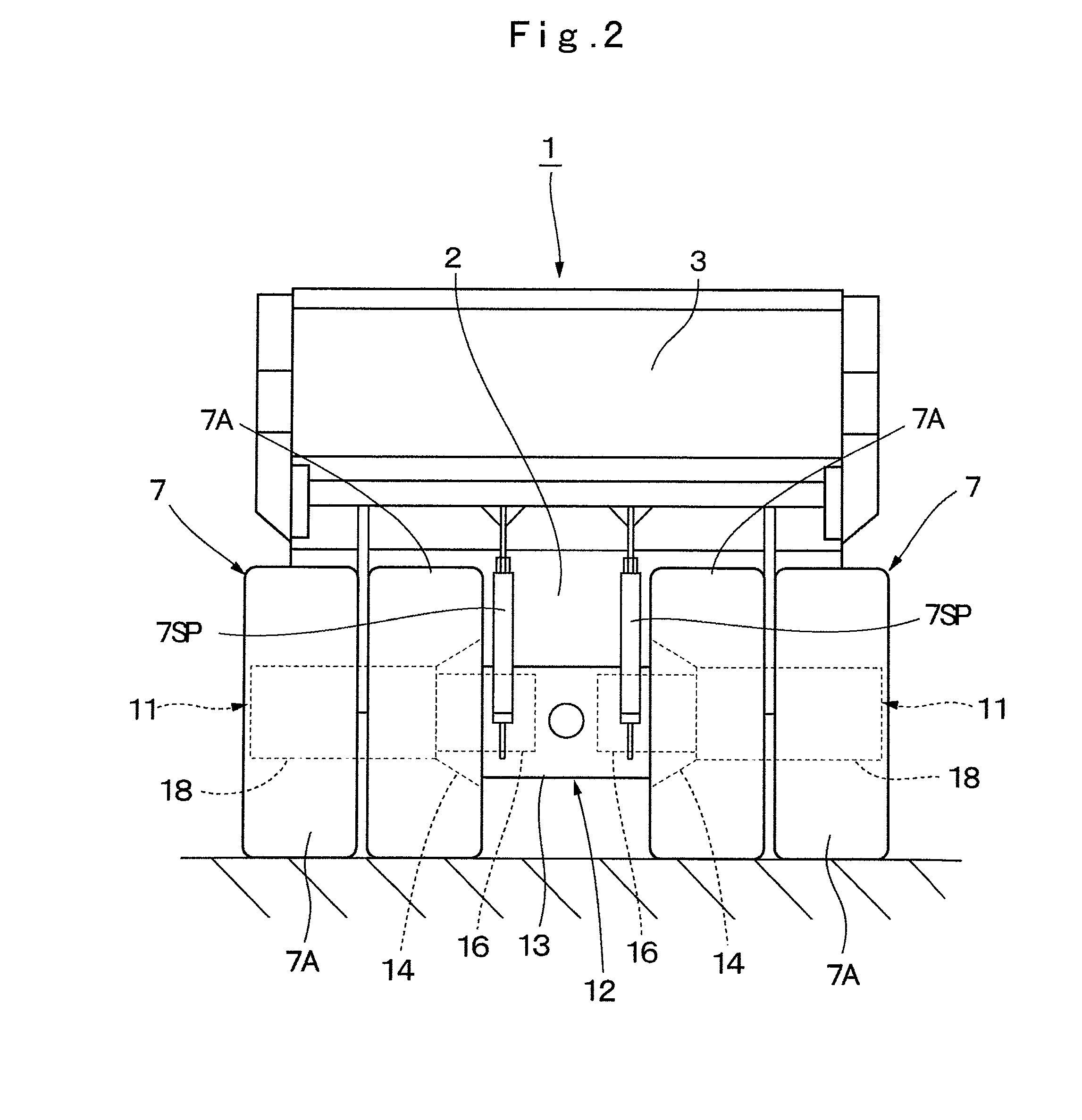
[0036]FIG. 1 to FIG. 5 show a travel drive device for a dump truck in the present invention.

[0037]In the figure, designated at 1 is a dump truck of a large-sized transporter vehicle adopted in the first embodiment. The dump truck 1 is constituted by including a vehicle body 2 having a strong frame structure and a vessel 3 as a loading platform liftably mounted on the vehicle body 2.

[0038]The vessel 3 is formed, for example, as a large-sized container of an entire length of 9 to 13 meters for loading a large volume of heavy baggage such as crushed stones. A rear-side bottom portion of the vessel 3 is liftably (tiltably) connected to a rear end side of the vehicle body 2 through a connecting pin 4. A protector 3A is integrally provided in a front-side top portion of the vessel 3 in such a manner as to cover a cab 5 to be described later from the upper side.

[0039]The cab 5 is provided in the front portion of the vehicle body 2 to be positioned under the protector 3A. The cab 5 forms a...

second embodiment

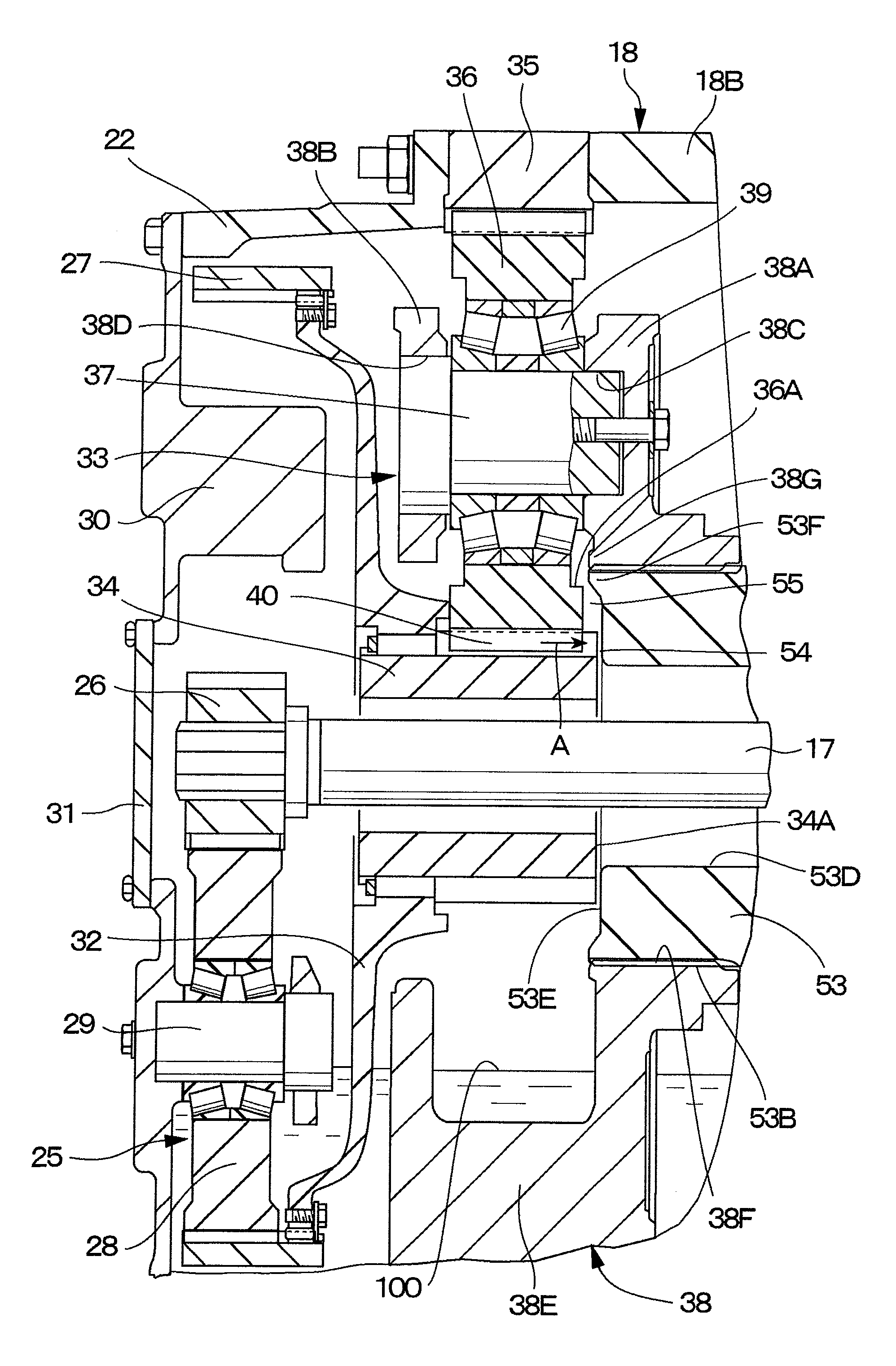
[0127]Particularly, in the second embodiment, the guide projection 62G which projects toward the axial one-side end surface 61A of the sun gear 61 is provided in the inner diameter side of the opposing surface portion 62E in the cylindrical coupling member 62. Therefore, the guide projection 62G beats off a part of the lubricant oil ejected from the meshing part 40 between the sun gear 61 and each of the planetary gears 36 toward a radial outside, and for example, causes the annular step portion 36A of the planetary gear 36 to trap and collect the beat lubricant oil, which can be supplied to a side of the planetary gear bearing 39.

[0128]It should be noted that in the aforementioned second embodiment, an explanation is made by taking a case where the guide projection 62G is configured of the annular projection extending over an entire circumference along the stepped hole 62D of the cylindrical coupling member 62, as an example. However, the present invention is not limited thereto, b...

third embodiment

[0139]Particularly, in the third embodiment, the plurality of the oil guide groove portions 73G radially extending are provided in the support plate 73A of the carrier 73, and the plurality of the oil guide groove portions 74F radially extending are provided also in the opposing surface portion 74E of the cylindrical coupling member 74. These oil guide groove portions 73G and 74F are arranged in positions to be communicated with each other. Therefore, the lubricant oil ejected from the meshing part 40 between the sun gear 71 and each of the planetary gears 72 can be guided between each of the planetary gears 72 and each of the support pins 37 along each of the oil guide groove portions 73G and 74F to maintain the planetary gear bearing 39 therebetween to be in a lubricating state.

[0140]Further, the plurality of the oil reservoirs 72A formed in the end surface of each of the planetary gears 72 can trap and temporarily reserve therein the lubricant oil ejected from the meshing part 40...


PUM


Abstract

A rotational shaft is provided in a spindle, a wheel mounting cylinder is provided which is mounted through wheel support bearings on an outer peripheral side of the spindle, and a planetary gear reduction mechanism is provided for decelerating rotation of the rotational shaft, which is transmitted to the wheel mounting cylinder. A carrier forming a part of the planetary gear reduction mechanism is mounted in a non-rotating state on an open end side of the spindle. A cylindrical coupling member is provided between an open side of the spindle and the carrier. An oil guide path is formed between a one-side end surface of each of planetary gears and an opposing surface portion of a cylindrical coupling member for guiding lubricant oil ejected from a meshing part therebetween to a planetary gear bearing.

Description

TECHNICAL FIELD[0001]The present invention relates to a travel drive device for a dump truck which is suitably used in transporting crushed stones excavated from such as an open-pit stope, a stone quarry or a mine.BACKGROUND ART[0002]In general, a large-sized transporter vehicle called a dump truck has a liftable vessel (loading platform) on a frame of a vehicle body, and transports crushed stones or the like in a state of the heavy baggage such as crushed stones being loaded in a large quantity on the vessel.[0003]Therefore, each travel drive device for driving drive wheels of the dump truck for traveling is provided with an axle housing mounted in a non-rotating state on a vehicle body and having a tip end side opened to form a cylindrical spindle, a rotational shaft provided to axially extend in the spindle of the axle housing and driven and rotated by a drive source, a wheel mounting cylinder which is rotatably mounted on an outer peripheral side of the spindle through wheel sup...

Claims


Application Information

Patent Timeline
Patent Type & Authority Patents(United States)
IPC IPC(8): F16H57/04
CPCF16H57/0479F16H57/0486B60K17/046B60Y2200/14F16H57/0457F16H1/46B60K7/0007B60K2007/0038B60K2007/0092B60Y2200/142
Inventor SHINOHARA, TAKESHISHIBUKAWA, TAKESHIHAGIHARA, SHINICHIROINOUE, NAOYUKITANAKA, KYOKO
Owner NIHON KENKI CO LTD
Why Eureka
Try Eureka