Method and system for reducing thermal protrusion of an NFT

a technology of thermal protrusion and nft, which is applied in the field of method and system for reducing thermal protrusion of an nft, can solve the problems of significant protrusion, significant loss of light energy from the laser, and partial deformation

Active Publication Date: 2013-10-22
WESTERN DIGITAL TECH INC
View PDF12 Cites 166 Cited by
  • Summary
  • Abstract
  • Description
  • Claims
  • Application Information

AI Technical Summary

Problems solved by technology

During operation, a significant amount of the light energy from the laser is lost in the form of local heating of the NFT 30.
Although the elastic portion of the deformation may be at least partially corrected by reducing the temperature, the plastic portion of the deformation may not be.
Further, the protrusion may be significant.
As a result, a portion of the NFT 30 may be ground away, which adversely affects performance and reliability of the transducer 10.
Such changes may reduce the efficiency of the NFT, which is undesirable.
Further, it may be difficult to find a material that has the required mechanical stability and optical efficiency at elevated temperature.

Method used


Image

  • Method and system for reducing thermal protrusion of an NFT
  • Method and system for reducing thermal protrusion of an NFT
  • Method and system for reducing thermal protrusion of an NFT

Examples


Embodiment Construction

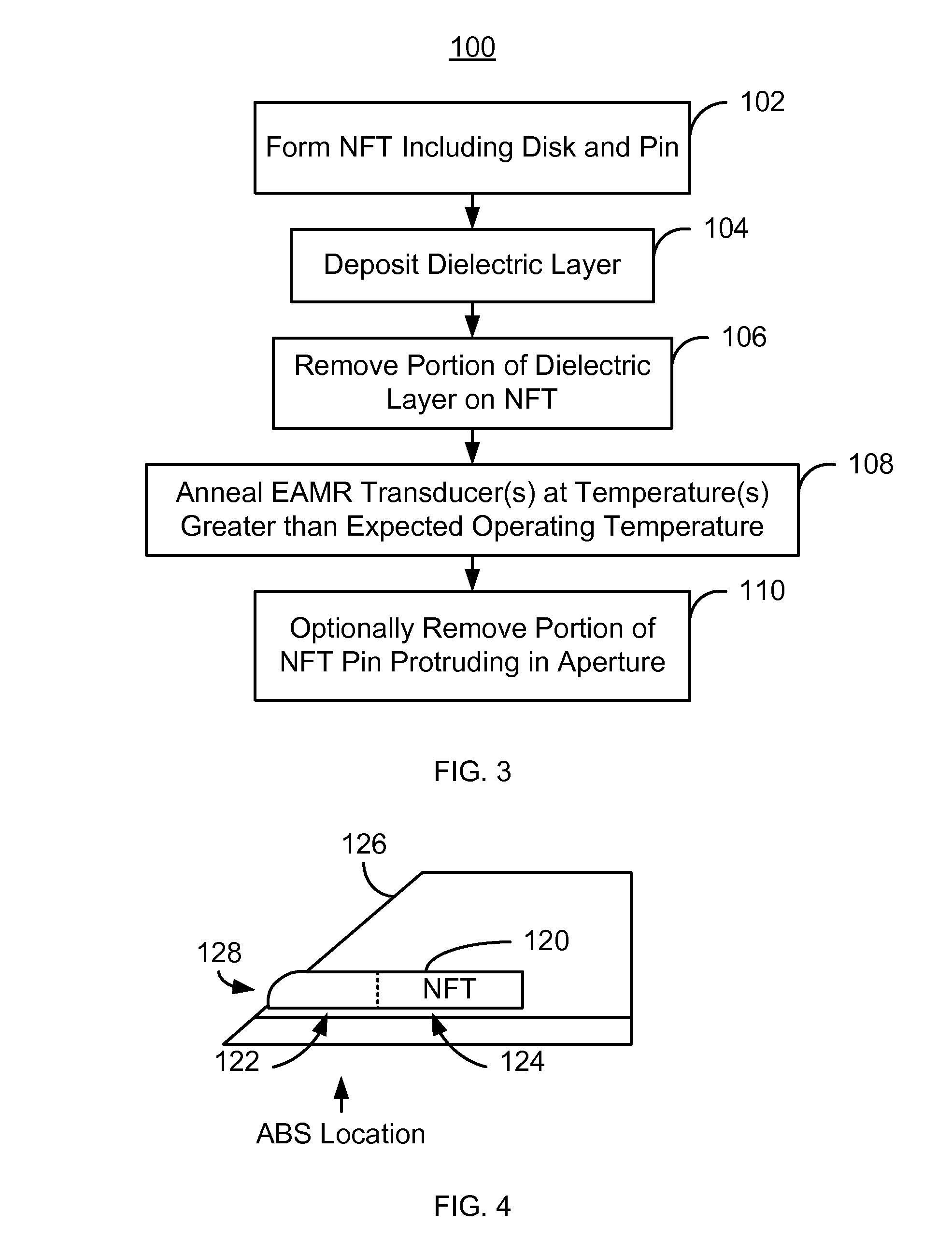
[0014]FIG. 3 depicts one embodiment of a method 100 for reducing the protrusion of an NFT in an EAMR transducer. The method 100 may thus be part of a method for fabricating the EAMR transducer. For simplicity, some steps may be omitted, interleaved, performed in another order and / or combined. The EAMR transducer may be part of a merged head that also includes a read head and resides on a slider in a disk drive. The method 100 is also described in the context of providing a single EAMR transducer. However, the method 100 may be used to fabricate multiple transducers at substantially the same time. The method 100 is also described in the context of particular layers. However, in some embodiments, such layers may include multiple sub-layers. The method 100 also may commence after formation of other portions of the EAMR transducer. In one embodiment, the method 100 commences after formation of portions of the EAMR transducer. For example, the method 100 may start after parts of the wave...


PUM

PropertyMeasurementUnit
temperatureaaaaaaaaaa

Abstract

A method and system provide a near-field transducer (NFT) for an energy assisted magnetic recording (EAMR) transducer. The method and system include forming an NFT having a disk and a pin. A dielectric layer that substantially covers the NFT is deposited. A portion of the dielectric layer is removed such that the dielectric layer has an aperture therein. The aperture exposes the pin of the NFT. The EAMR transducer is annealed at a temperature greater than the expected operating temperature of the EAMR transducer.

Description

BACKGROUND[0001]FIGS. 1A and 1B depict a portion of a conventional energy assisted magnetic recording (EAMR) transducer 10. The conventional EAMR transducer 10 includes a conventional waveguide 12 having a conventional core 18 and cladding 14 and 16, a grating 20, a conventional near-field transducer (NFT) 30, and a write pole 40. The NFT 30 has a disk portion 34 and a pin portion 32. The pin portion 32 is between the disk portion 34 and the air-bearing surface (ABS). The conventional EAMR transducer 10 is used in writing to a recording media and receives light, or energy, from a conventional laser (not shown).[0002]In operation, light from a laser is coupled to the waveguide 12. Light is guided by the conventional waveguide 12 to the NFT 30 near the ABS. The NFT 30 utilizes local resonances in surface plasmons to focus the light to magnetic recording media (not shown), such as a disk. The surface plasmons used by the NFT 30 are electromagnetic waves that propagate along metal / diele...

Claims


Application Information

Patent Timeline
Patent Type & Authority Patents(United States)
IPC IPC(8): G11B11/00
CPCG11B5/3136G11B5/314G11B5/6088G11B5/3173G11B2005/0021
Inventor TANNER, SHAWN M.HU, YUFENG
Owner WESTERN DIGITAL TECH INC
Why Eureka
Try Eureka