Insect capture device and system
- Summary
- Abstract
- Description
- Claims
- Application Information
AI Technical Summary
Benefits of technology
Problems solved by technology
Method used
Image
Examples
Embodiment Construction
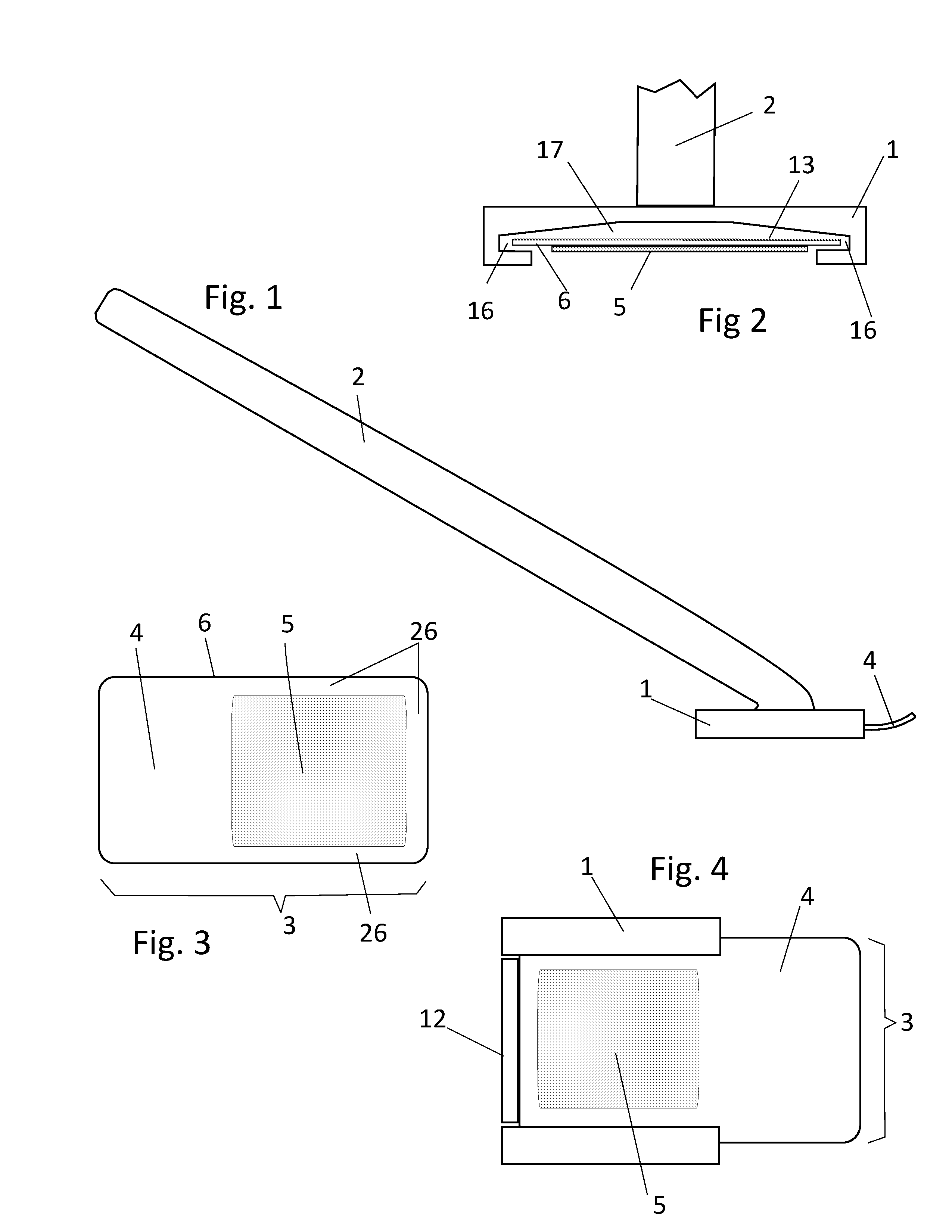
[0021]FIG. 1 illustrates a side view of the insect capture device with the handle 2, the holder 1, and the holding tab 4 of the capture sheet (not completely shown here) emerging from the front of the holder. As shown, the handle 2 is an elongated tube or rod fixed at one end to the holder 1. The handle 2 may be pivotally or fixedly connected to the holder 1. Additionally, the handle 2 may be formed as a telescoping device (not shown) whereby its length may be adjusted by a user.
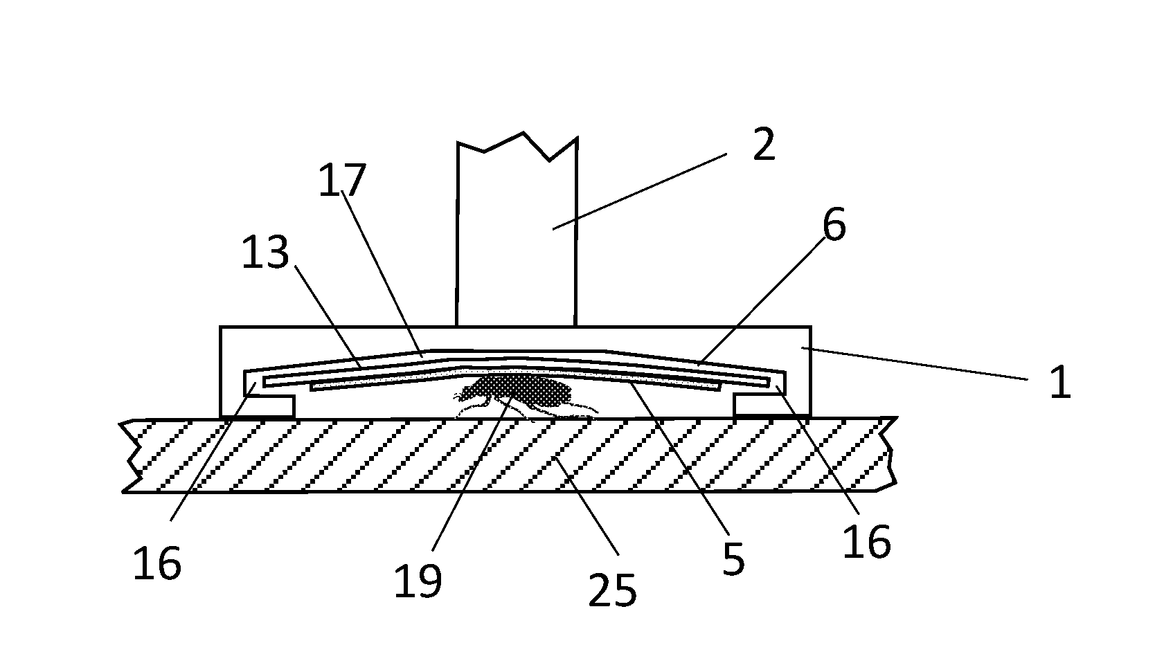
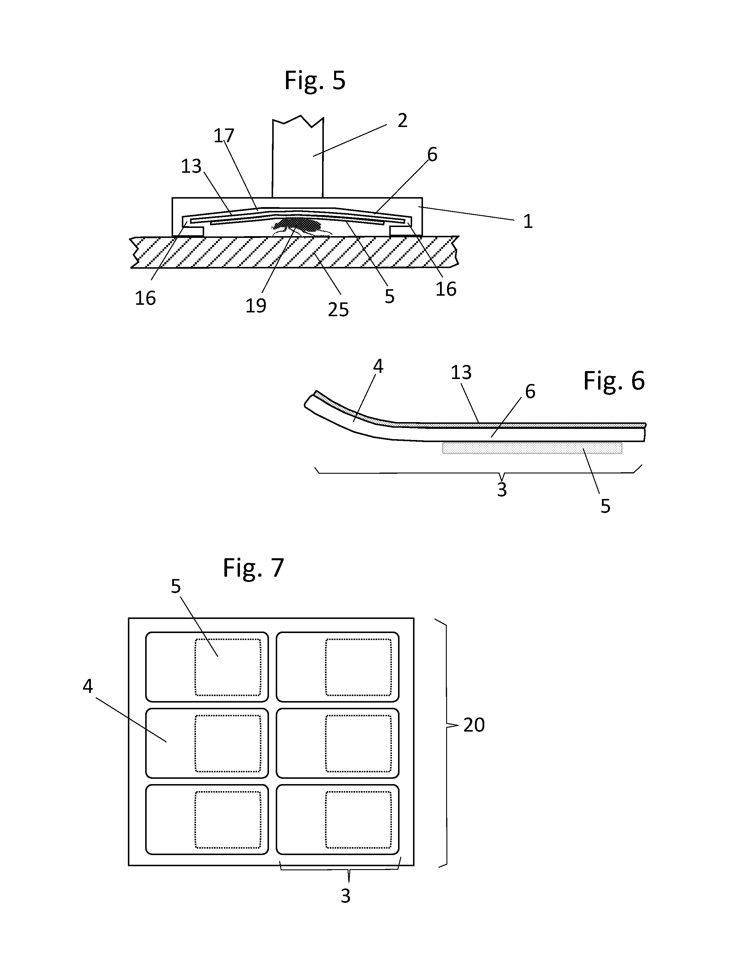
[0022]FIG. 2 is a front view of the holder 1, the lower portion of the handle 2, the grooves 16 in the underside of the holder, the concave cavity 17 above the capture sheet's base sheet 6, the adhesive coating 5, and a release coating 13 on top of the base sheet. Note that the layers are not necessarily shown in their correct relative thicknesses. As shown, the holder 1 is formed as a generally planar member having a cavity 17 and grooves 16 to receive a capture sheet 3 along opposite lateral edges of the b...
PUM
 Abstract
Description
Claims
Application Information
 - R&D
- Intellectual Property
- Life Sciences
- Materials
- Tech Scout
- Unparalleled Data Quality
- Higher Quality Content
- 60% Fewer Hallucinations
Browse by: Latest US Patents, China's latest patents, Technical Efficacy Thesaurus, Application Domain, Technology Topic, Popular Technical Reports.
© 2025 PatSnap. All rights reserved.Legal|Privacy policy|Modern Slavery Act Transparency Statement|Sitemap|About US| Contact US: help@patsnap.com


