

Method of forming an abrasive coating on a fan blade tip
Active Publication Date: 2016-11-10
RAYTHEON TECH CORP
View PDF11 Cites 4 Cited by
- Summary
- Abstract
- Description
- Claims
- Application Information
AI Technical Summary
Benefits of technology
The method described in this patent describes a way to make a surface easier for grit particles to stick to. This is important because the method does not need to heat up the surface to create a soft surface, which could damage the fan blade. An easy way to do this is to use an extra heat source to create a soft and heated area where the grit particles can stick to. This makes it more likely that the grit particles will stick to the surface, which helps in capturing them.
Problems solved by technology
The softened surface greatly increases the probability of grit capture.
Method used
View moreImage
Smart ImageViewing Examples

Examples
example
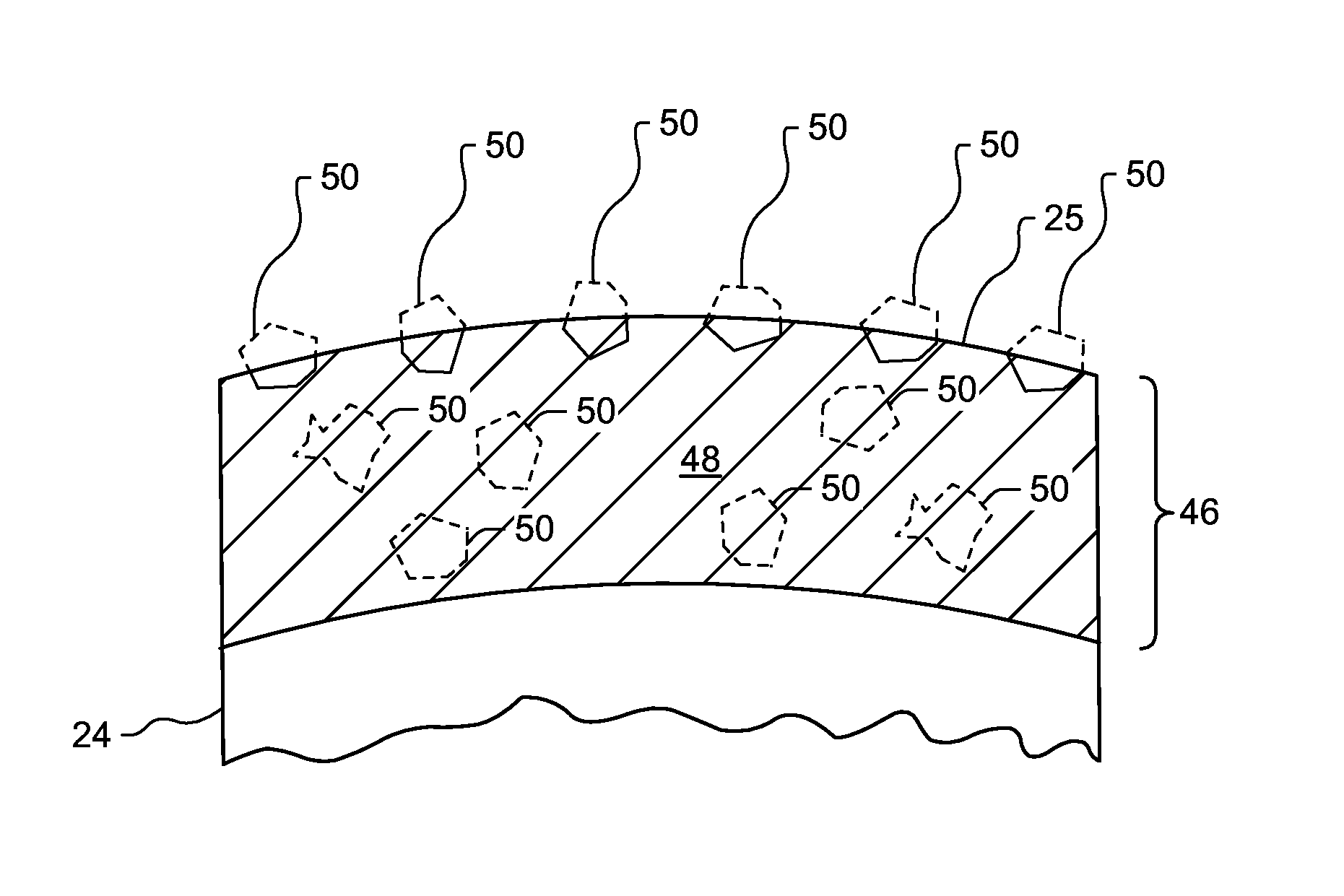
[0054]The method described herein has been shown to result in a deposition efficiency of about 45% (measured as the percentage of grit particles 50 that stick to the metal matrix coating 48) compared to about 5.6% in baseline methods. This increase in deposition efficiency results in an increase in grit concentration in the abrasive coating 46, and higher wear resistance in service.
Login to View More PUM
| Property | Measurement | Unit |
|---|---|---|
| Mass flow rate | aaaaa | aaaaa |
| Mass flow rate | aaaaa | aaaaa |
| Mass flow rate | aaaaa | aaaaa |
Abstract
A novel method of depositing grit particles onto a fan blade tip coating is provided. The method enhances grit capture by presenting a softened coating surface for the impinging particles. The softened surface is achieved without high substrate temperatures that could degrade the base metal properties in the fan blade. An auxiliary heat source is used to establish a locally heated and softened surface where the grit deposition takes place. The softened surface greatly increases the probability of grit capture.
Description
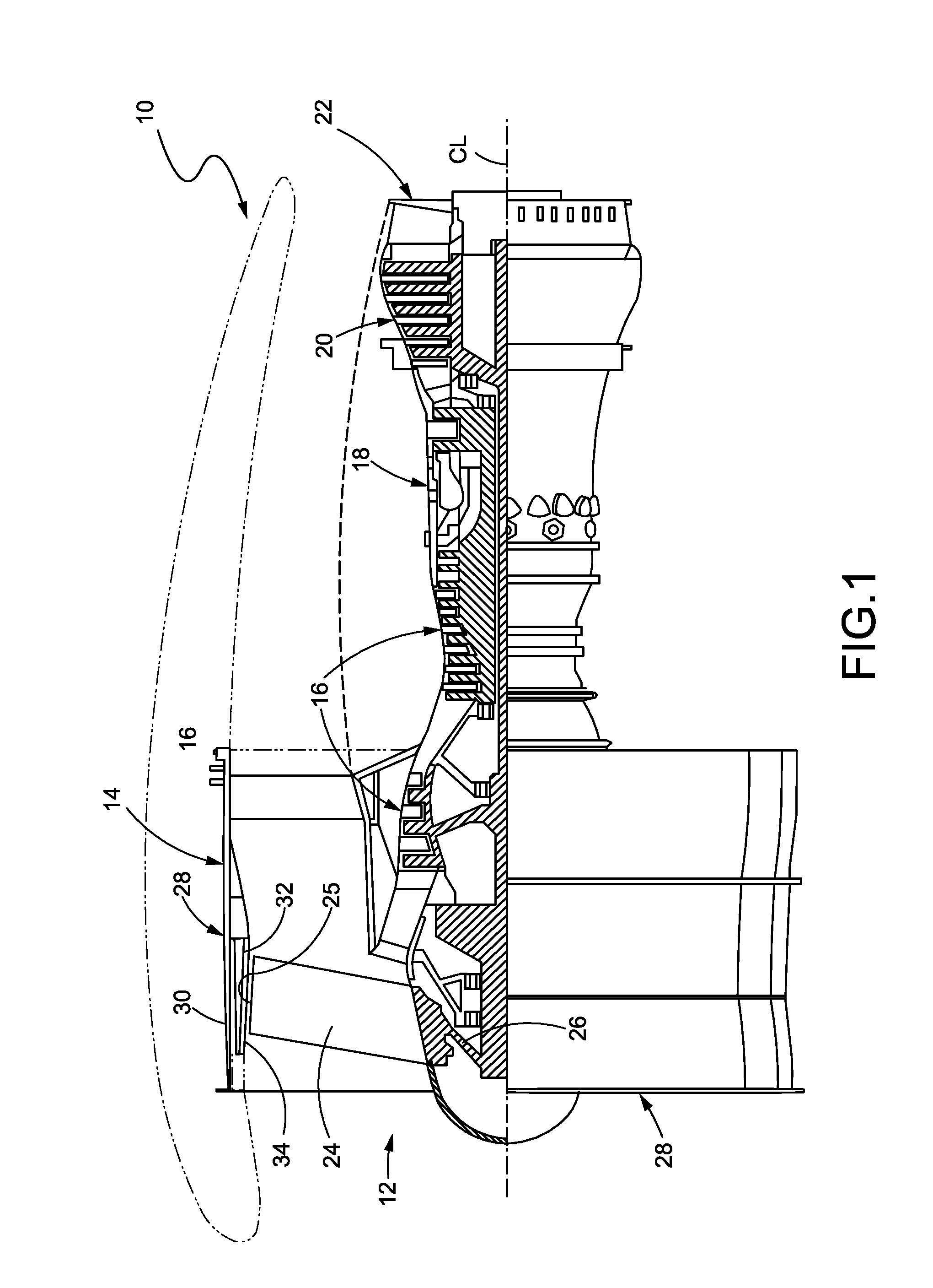
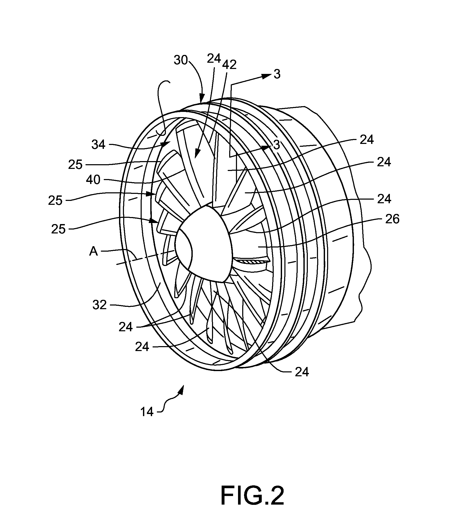
FIELD OF THE DISCLOSURE[0001]The subject matter of the present disclosure relates generally to a method of finishing a rotating turbomachine component such as a fan blade. More particularly, the subject matter relates to a method of forming an abrasive coating on a fan blade tip of the type used in gas turbine engines.BACKGROUND OF THE DISCLOSURE[0002]Gas turbine engines, such as those used on jet aircraft, generally comprise an air intake port, a fan section, a low pressure compressor (LPC) section, an intermediate section aft of the LPC section, a high pressure compressor (HPC) section, a combustion chamber or combustor, high and low pressure turbines that provide rotational power to the compressor blades and fan respectively, and an exhaust outlet. The fan and LPC section may be operably connected to the low pressure turbine by an inner drive shaft which rotates about an engine center axis. A cone-like spinner may be mounted over the hub forward the fan blades to help guide air f...
Claims
Login to View More Application Information
Patent Timeline
 IPC IPC(8): C23C4/08F01D5/28C23C4/18
CPCC23C4/08F01D5/288C23C4/18C23C4/06C23C4/12C23C4/123C23C4/134F01D11/122F05D2300/121F05D2230/312Y02T50/60
InventorSTROCK, CHRISTOPHER W.LUTJEN, PAUL M.
OwnerRAYTHEON TECH CORP