Powering a vehicle and providing excess energy to an external device using photovoltaic cells

Inactive Publication Date: 2006-06-08
FLORIDA ATLANTIC UNIVERSITY
View PDF16 Cites 196 Cited by
  • Summary
  • Abstract
  • Description
  • Claims
  • Application Information

AI Technical Summary

Benefits of technology

[0012] The present invention provides for the enhanced capture of solar energy using an array of photovoltaic cells carried by a self-propelled vehicle. The enhanced capture is a result of being able to affect key variables, such as the angle of incidence of sunlight on the photovoltaic cells and the energy transfer across an array-battery interface. The end result of capturing more solar energy is that relatively greater amounts of p

Problems solved by technology

An inherent problem in powering any device using a photovoltaic array is that is often difficult to optimize the variables that determine how much power is generated by the array.
For example, a fundamental problem relates to the first of the above-listed variables.
The problem stems from the fact that a system designer can not predict when and how much sunlight will be available.
But designing a system to influence even the other variables that can be directly influenced has proved to be almost as problematic.
Nevertheless, a failure to optimize these variables means that the power generated by a photovoltaic array is likely to be less than the maximum that the photovoltaic array could otherwise provide.
The problem of optimizing these variables tends to be even more pronounced in the context of attempting to power an electric cart or similar type vehicle using a photovoltaic array.
Achieving a more favorable alignment, however, is made all the more difficult by the fact that the vehicle may have to be stationed on a surface whose angle adversely affects the angle of incidence of sunlight on a photovoltaic array fixedl

Method used


Image

  • Powering a vehicle and providing excess energy to an external device using photovoltaic cells
  • Powering a vehicle and providing excess energy to an external device using photovoltaic cells
  • Powering a vehicle and providing excess energy to an external device using photovoltaic cells

Examples


Example

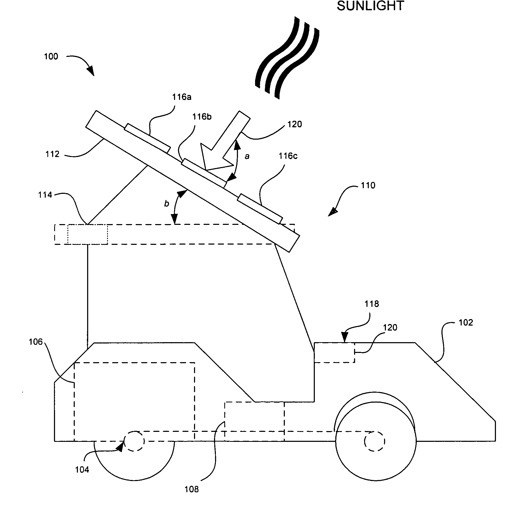
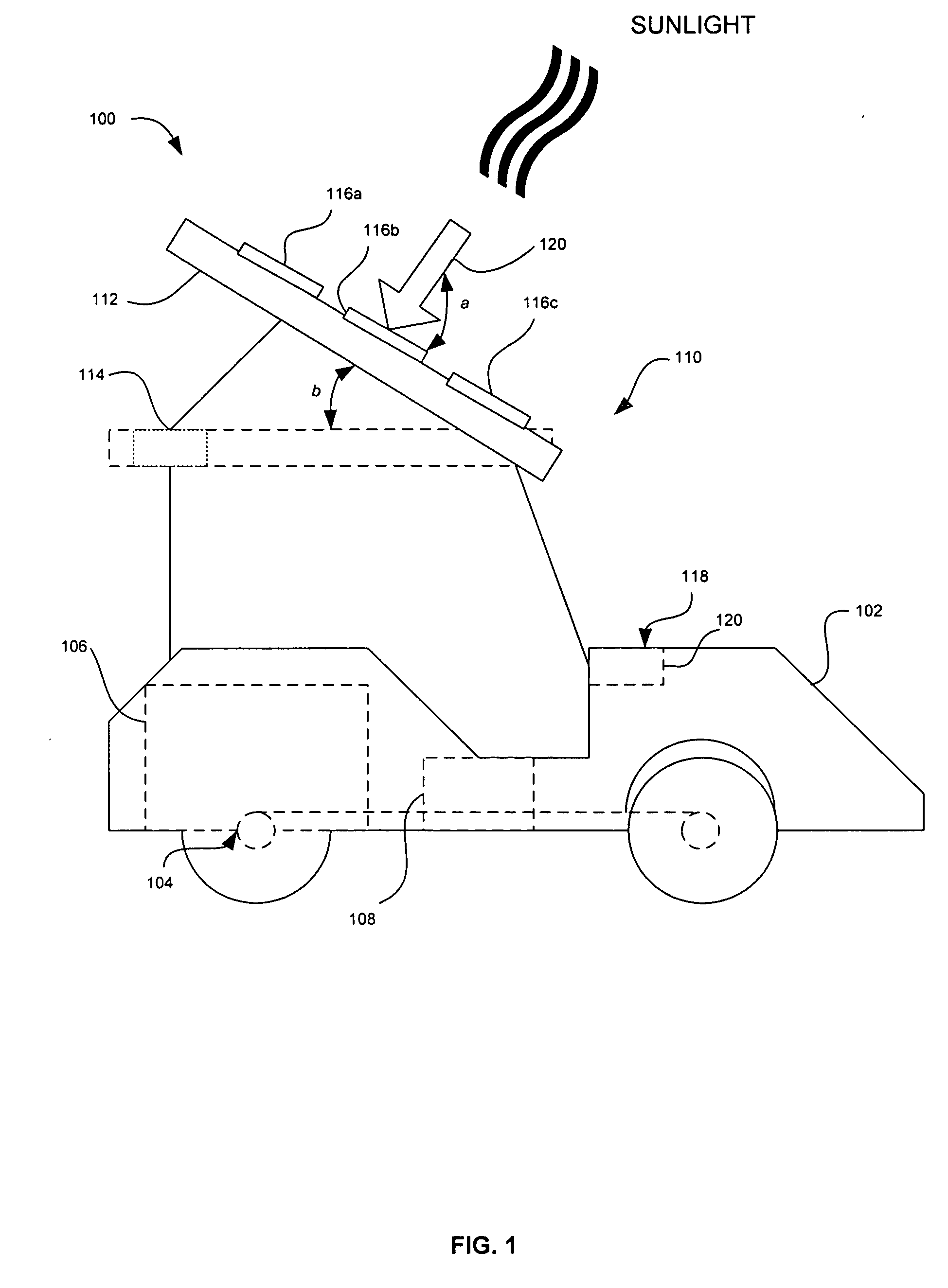
[0034]FIG. 1 is a schematic diagram of a self-propelled vehicle 100 according to one embodiment of the present invention. The vehicle 100 illustratively includes a vehicle body 102 and a vehicle propulsion mechanism 104 for propelling the vehicle body over a surface. The vehicle propulsion mechanism 104 is illustratively driven by a vehicle motor 106 carried in or mounted on the vehicle body 102. The vehicle motor 106 is illustratively powered by a battery 108, which is also carried in or mounted on the vehicle body 102. As further illustrated, the vehicle 100 includes a photovoltaic powering system 110 carried by the vehicle body 102.

[0035] The size and shape of the vehicle body 102 can vary depending on the function that the vehicle 100 performs and / or the environment in which it is used. For example, the vehicle 100 can be used to transport one or more individuals within a campus or recreational environment, such as a university campus or a golf course, in which case the vehicle...


PUM


Abstract

A photovoltaic powering system is provided that includes a movable platform connected to a self-propelled vehicle. An array of one or more photovoltaic cells is carried by the movable platform. A platform movement mechanism carried by the vehicle moves the movable platform. A platform alignment module carried by the vehicle and connected to the platform movement mechanism causes the photovoltaic cells to be aligned relative to ambient sunlight. The one or more photovoltaic cells converts ambient sunlight to energy that is supplied to a battery carried by the vehicle to thereby recharge the battery if a charge associated with the battery is less than a predetermined threshold.

Description

BACKGROUND OF THE INVENTION [0001] 1. Field of the Invention [0002] The present invention is related to the field of power generation, and, more particularly, to the generation of energy for powering a vehicle, as well as equipment carried by the vehicle, and for supplying excess energy to an external device or power grid. [0003] 2. Description of the Related Art [0004] Electrical carts are vehicles whose relatively small size, low noise, and relatively low power consumption have long made them the vehicle of choice on many academic and business campuses as well as most golf courses throughout the world. In recent times, there have been attempts to power such vehicles with solar energy. These attempts have tended to center around devising arrays of photovoltaic cells that can be carried by such vehicles to provide a primary or secondary source of power. [0005] A photovoltaic cell is an energy conversion device for converting solar energy into electrical energy. The typical photovolt...

Claims


Application Information

Patent Timeline
IPC IPC(8): H01L25/00
CPCB60L8/00H02S40/38B60L2200/22H01L31/042H02J3/38H02J7/0027H02J7/35Y02T10/7005Y02T10/7055Y02T10/7083Y02T10/7094Y02T90/14Y02E10/50Y04S10/126Y02E60/721H02S20/00B60L11/1816H02S20/30H02S10/40Y02T10/7072B60L53/14H02J2310/48Y02T10/70Y02E70/30H02J3/322Y04S30/12Y02T90/167Y02E60/00
Inventor SAELZER, MAXMESSENGER, ROGER
Owner FLORIDA ATLANTIC UNIVERSITY
Why Eureka
Try Eureka