
Zero backlash preload gears

a technology of preloading gears and gears, applied in the direction of gearing elements, belts/chains/gearrings, hoisting equipments, etc., can solve the problems of increasing costs, achieve the effect of ensuring accuracy and reliability of the system, and reducing the cost of per position

Active Publication Date: 2013-10-29
GENESIS SYST GROUP L L C
View PDF11 Cites 6 Cited by
  • Summary
  • Abstract
  • Description
  • Claims
  • Application Information

AI Technical Summary

Benefits of technology

The solution achieves accurate and reliable positioning with reduced backlash, enabling tighter manufacturing tolerances and efficient use of space without additional per-position expenses or secondary positioning apparatuses, thereby enhancing the operational range and reliability of automated robots.

Problems solved by technology

However, the “hard stop” setup allows only two indexed positions.
For more complicated processes requiring several stations, multiple tables must be set up, increasing expense.

Method used


Image

  • Zero backlash preload gears
  • Zero backlash preload gears
  • Zero backlash preload gears

Examples


Embodiment Construction

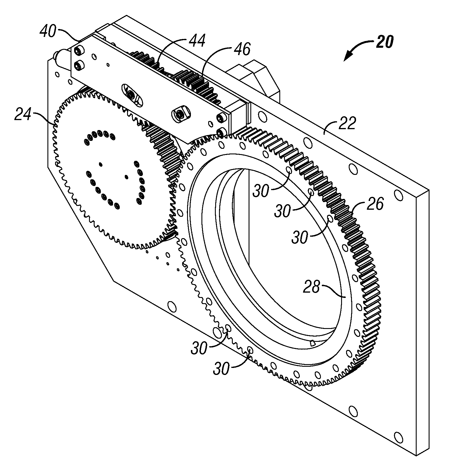
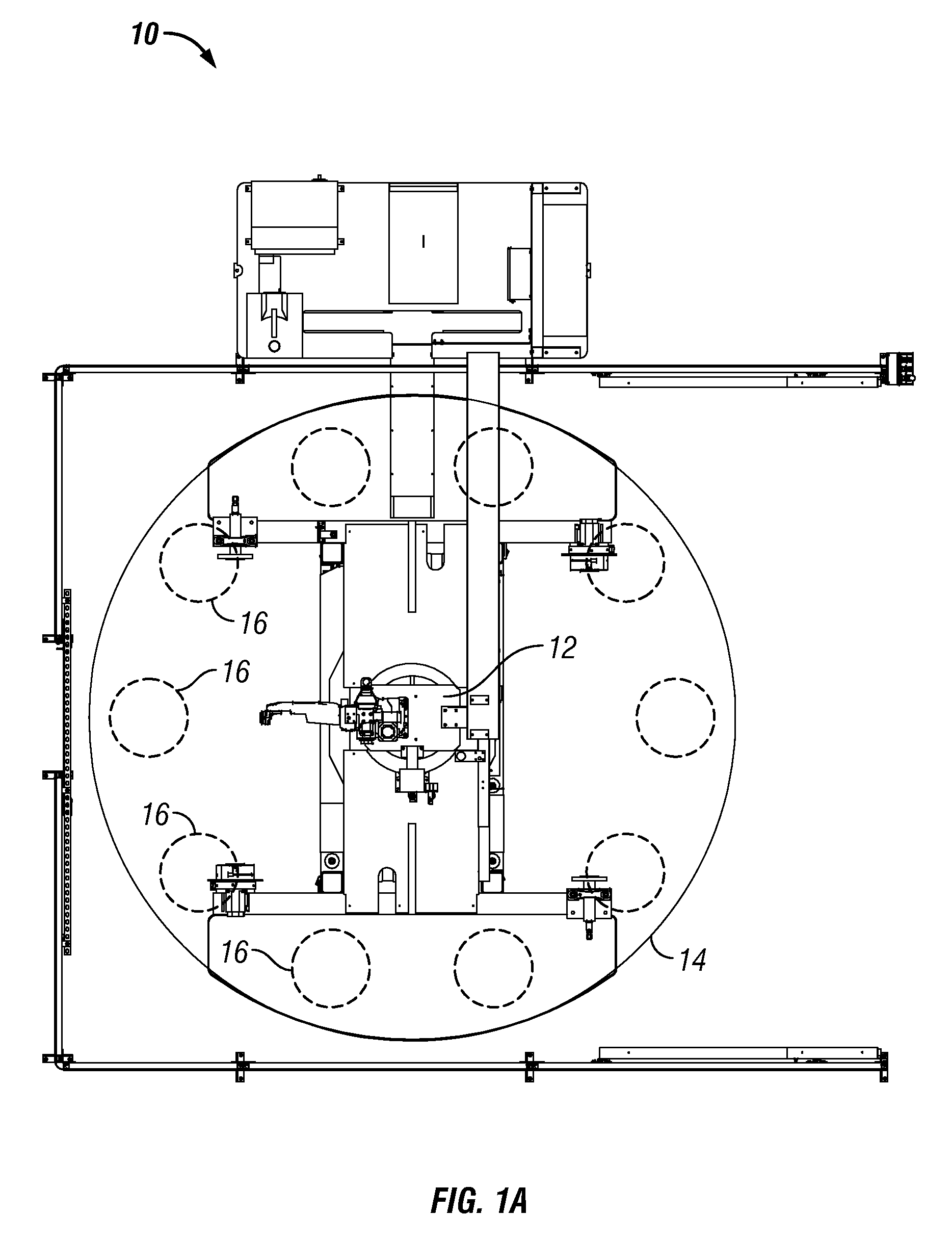
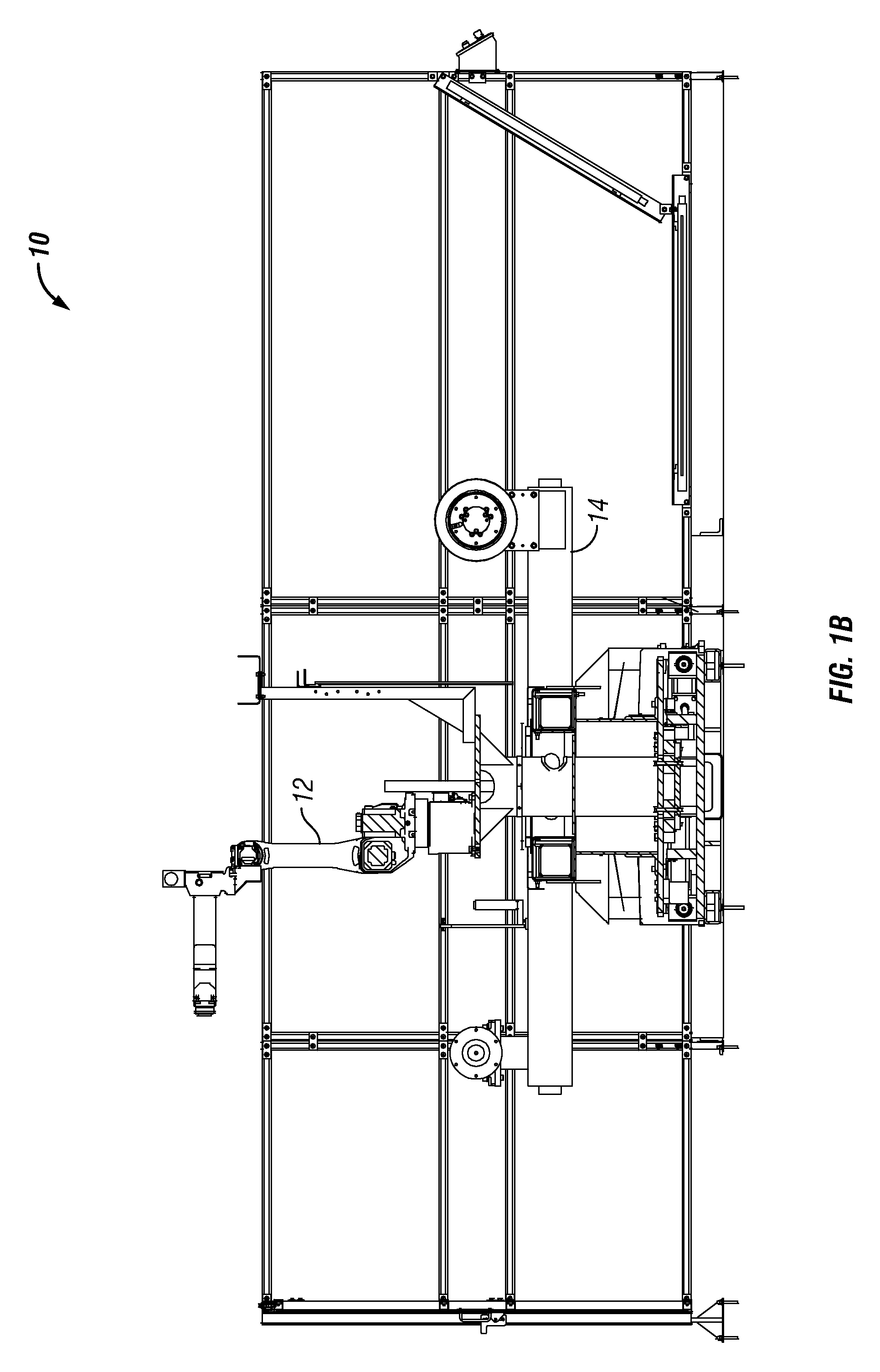
[0028]The zero-backlash preload gear assembly and positioning device 10 will now be described in detail according to the preferred embodiment with reference to the attached figures where numerals relate to their like in the following description.

[0029]The terms “leading edge” and “trailing edge” of the teeth of a gear will be used within this description. The term “leading edge” and “trailing edge” are intended to indicate the faces of an individual gear tooth. Each term is described with reference to the direction of movement of the gear; for example if a gear is being rotated in a clockwise direction, then the “leading edge” is the clockwise-ward face of the gear tooth, while the counter-clockwise (also known as “contra-clockwise”, “anticlockwise”, or abbreviated “CCW”) face of the gear tooth represents the “trailing edge.” In the case of gear interaction, force will always be transferred from the “leading edge” of a tooth on a drive gear to the “trailing edge” of a tooth on a dri...


PUM


Abstract

Described in this application is a zero-backlash preload gear assembly. The assembly is specifically described for use with a positioning system in order to significantly reduce or eliminate mechanical error and improve tolerances. Furthermore, the assembly allows for infinite positioning of a work surface in order to facilitate improved efficiency of an automated system.

Description

FIELD OF THE INVENTION[0001]The present invention relates to positioning apparatus and methods and mechanisms to eliminate or substantially reduce backlash in gearing control systems in a positioning apparatus.BACKGROUND OF THE INVENTION[0002]Automated servo-driven robots are increasingly becoming a staple in manufacturing settings. From welding to assembly, these machines are capable of performing repetitive tasks with relatively low per-unit expenses. In order to achieve the optimum quality work from such a robot, materials must be positioned at proper positions with only minor variation, defined as manufacturing tolerances.[0003]It is common practice to mount material onto a circular platform having one or more indexed positions. This allows a worker to position materials on one station while the robot is performing the selected operation, for example welding. By providing hard stops between the platform and base to which the table is mounted, the indexed positions can be placed ...

Claims


Application Information

Patent Timeline
Patent Type & Authority Patents(United States)
IPC IPC(8): F16H55/18
CPCF16H57/12F16H2057/126Y10T74/19623Y10T74/19898F16H2057/121
Inventor MANGELSEN, JAN CHRISTIANROHRET, RICHARD DEANSCHILB, CHRISTOPHER J.
Owner GENESIS SYST GROUP L L C
Learn More