
Projectile launching device

a projectile and launcher technology, applied in the field of man-powered weapons, can solve the problems of heavy front end of traditional crossbows and difficulty in manipulating

Inactive Publication Date: 2013-10-29
FLINT WILSON
View PDF7 Cites 36 Cited by
  • Summary
  • Abstract
  • Description
  • Claims
  • Application Information

AI Technical Summary

Benefits of technology

The present invention is a projectile launcher that uses elastomeric drive units to provide a high momentum launch for projectiles. The launcher design can push or pull the projectile for acceleration during launch. The design also includes a noise-suppression tube and a braking mechanism for the sled. Additionally, an adaptation of the invention involves a three-string structure for use with the accelerators and a separate drive string for each accelerator. The invention also includes a compound bow design that achieves a non-linear increase in the draw cam radius and a simultaneous decrease in the drive cam radius to achieve a combined action similar to a compound bow. The technical effects of the invention include improved noise suppression, high acceleration, and efficient launching of projectiles.

Problems solved by technology

Most notably, a traditional crossbow is front-end heavy and, consequently, is somewhat difficult to manipulate during hunting.

Method used


Image

  • Projectile launching device
  • Projectile launching device
  • Projectile launching device

Examples


Embodiment Construction

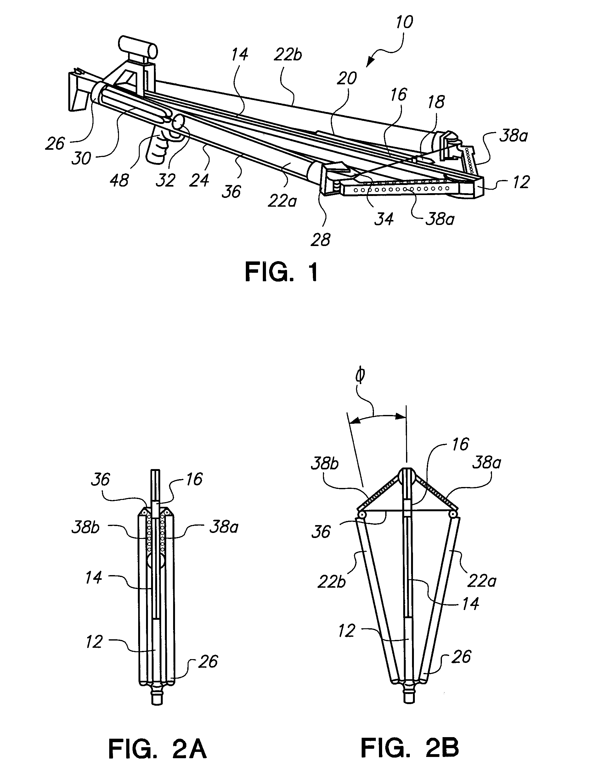
[0024]Referring initially to FIG. 1, a projectile launcher in accordance with the present invention is shown and is generally designated 10. As shown, the launcher 10 includes a base member 12 that is formed with an acceleration rail 14. Further, a sled 16 is shown mounted on the acceleration rail 14 for reciprocal movement thereon. A projectile is also shown in FIG. 1, with the projectile having a projectile head 18, with an elongated projectile shaft 20 extending from the projectile head 18. More specifically, the projectile head 18 is shown engaged with the sled 16. Preferably, this engagement is accomplished magnetically.

[0025]Still referring to FIG. 1, it will be seen that the launcher 10 includes a pair of accelerators 22a and 22b. In detail, the accelerators 22a and 22b each include a noise suppression tube 24 and they are positioned on opposites sides of the base member 12. Using the accelerator 22a as an example for disclosure purposes, it will be seen that the accelerator ...


PUM


Abstract

A projectile launcher includes an acceleration rail with an accelerator mounted on opposite sides of the rail. Each accelerator includes an elastomeric energy generator having an end that is held stationary, while another end is connected to a string. This string then passes over a series of pulleys and crosses over the rail into the other accelerator. Thus, both accelerators act on the same string. In operation, as the string is pulled back and engaged with the projectile on the acceleration rail, the elastomeric drives are stretched. Also, each series of pulleys effectively causes a velocity multiplication that enhances the momentum of the projectile when it is launched.

Description

[0001]This application claims the benefit of U.S. Provisional Patent Application Ser. No. 61 / 324,209, filed Apr. 14, 2010.FIELD OF THE INVENTION[0002]The present invention pertains generally to man-powered weapons. More particularly, the present invention pertains to weapons that allow an individual to configure the weapon with their own physical strength, to thereby establish sufficient energy for effectively launching projectiles with a momentum required for activities such as “big game” hunting. The present invention is particularly, but not exclusively, useful as a man-powered weapon that can be handled, aimed and operated with enhanced power and accuracy.BACKGROUND OF THE INVENTION[0003]All man-powered weapons rely on the inherent capability of the weapon to be operationally armed by an individual. Essentially, this means that a single individual must be able to, somehow, reconfigure or manipulate the weapon so that it has sufficient potential energy to effectively launch a pro...

Claims


Application Information

Patent Timeline
Patent Type & Authority Patents(United States)
IPC IPC(8): F41B3/02F41B5/12
CPCF41B5/12
Inventor FLINT, WILSON
Owner FLINT WILSON
Learn More