Method for forming single-phase multi-element film by PEALD

a multi-element film, single-phase technology, applied in the direction of coatings, chemical vapor deposition coatings, metallic material coating processes, etc., can solve the problems of insufficient etch selectivity of mono-element si-based insulation films, base substrates or photoresists are vulnerable to deformation, and the operation is complicated and requires more steps

Active Publication Date: 2013-10-29
ASM JAPAN
View PDF11 Cites 385 Cited by
  • Summary
  • Abstract
  • Description
  • Claims
  • Application Information

AI Technical Summary

Problems solved by technology

Although depending on the type of reactant, a base substrate or a photoresist is vulnerable to deformation due to plasma damage caused when the mono-element Si-based insulation film is exposed to a plasma, and the etch selectivity of the mono-element Si-based insulation film is insufficient.
Since the above method uses two different types of cycle (i.e., a cycle for a SiC sub-layer, and another cycle for a SiO sub-layer), more steps and more complicated operation are required as compared with a method using a single type of cycle.

Method used


Image

  • Method for forming single-phase multi-element film by PEALD
  • Method for forming single-phase multi-element film by PEALD
  • Method for forming single-phase multi-element film by PEALD

Examples


example 1

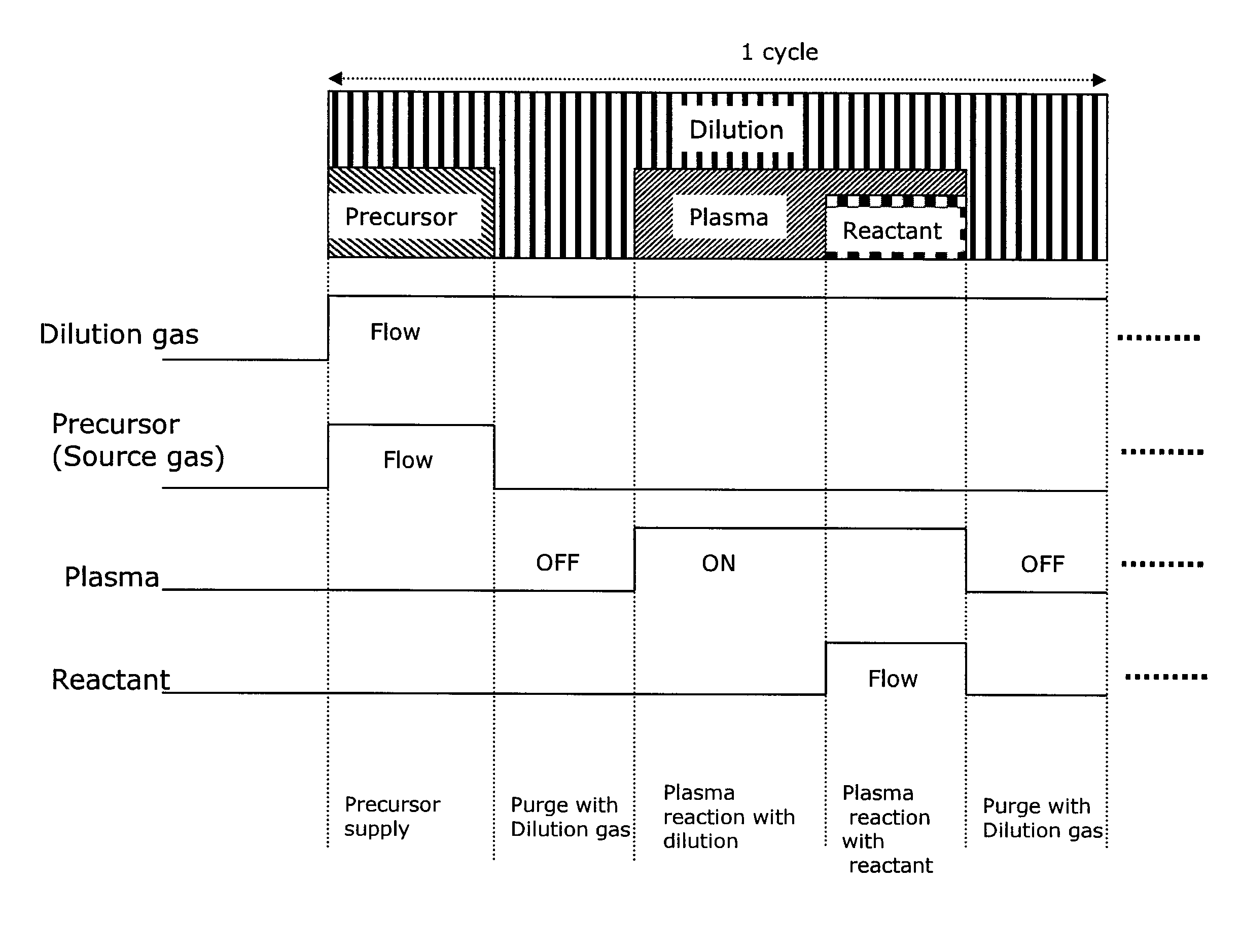
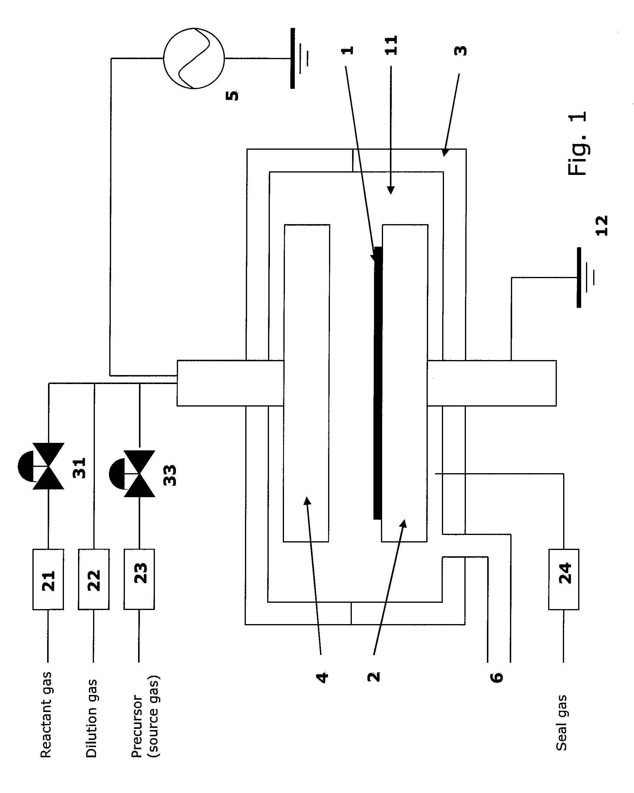
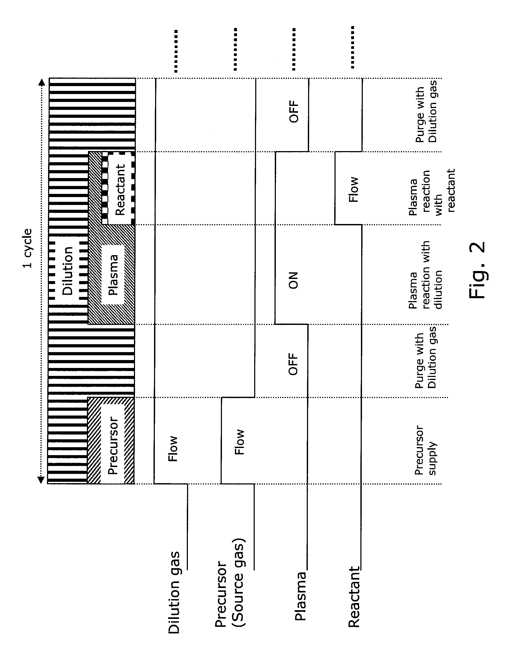
[0057]A dielectric multi-element SiOX film was formed on a 300-mm substrate under the conditions shown below using the sequence illustrated in FIG. 2 and the PEALD apparatus illustrated in FIG. 1. In this example, X was C and N.

[0058]The length of one cycle: 3.1 sec to 4.1 sec

[0059]Precursor: BDEAS: 500 sccm to 1,000 sccm

[0060]Dilution gas: He: 2000 sccm

[0061]Reactant gas: O2: 30 sccm

[0062]Seal gas: He: 500 sccm

[0063]Substrate temperature: 100° C.

[0064]Pressure: 230 Pa

[0065]High frequency RF power (a frequency of 13.56 MHz): 0.08 W / cm2

[0066]Precursor supply pulse duration: 1.5 sec

[0067]Purge time: 0.3 sec

[0068]The total duration of dilution gas plasma and reactant gas plasma: 1.0 sec

[0069]The number of cycles: 600 times

[0070]The thickness of the film: 10 nm to 20 nm

[0071]The duration of reactant gas plasma was changed from 0 sec to 1.0 sec while maintaining the total duration of dilution gas plasma and reactant gas plasma, 1.0 sec. The refractive index at 633 nm of each resultant f...

example 2

[0074]A dielectric multi-element SiCON film was formed on a 300-mm substrate under the conditions shown below using the sequence illustrated in FIG. 2 and the PEALD apparatus illustrated in FIG. 1.

[0075]The length of one cycle: 2.5 sec

[0076]Precursor: BDEAS: 500 sccm

[0077]Dilution gas: Ar, He: 1000 sccm

[0078]Reactant gas: O2: 40 sccm at maximum

[0079]Seal gas: He: 500 sccm

[0080]Substrate temperature: 50° C.

[0081]Pressure: 200 to 300 Pa

[0082]High frequency RF power (a frequency of 13.56 MHz): 0.07 W / cm2

[0083]Precursor supply pulse duration: 0.5 sec

[0084]Purge time: 0.3 sec

[0085]The duration of dilution gas plasma: 1.0 sec

[0086]The duration of reactant gas plasma: 0.4 sec at maximum

[0087]The number of cycles: 100 times

[0088]The thickness of the film: 10 nm

[0089]After the target multi-element SiCON film was obtained, the composition of the resultant film was analyzed by XPS (Narrow Scan Overlay), and the result is shown in the table below. Since the film was thin, the composition was a...


PUM

PropertyMeasurementUnit
RIaaaaaaaaaa
pressureaaaaaaaaaa
pressureaaaaaaaaaa

Abstract

A method for forming a single-phase multi-element film on a substrate in a reaction zone by PEALD repeating a single deposition cycle. The single deposition cycle includes: adsorbing a precursor on the substrate in the absence of reactant and plasma; decomposing the precursor adsorbed on the substrate by an inert gas plasma; and reacting the decomposed precursor with a reactant gas plasma in the presence of the inert gas plasma. The multi-element film contains silicon and at least two non-metal elements constituting a matrix of the film, the precursor contains silicon and optionally at least one non-metal element to be incorporated in the matrix, and the reactant gas contains at least one non-metal element to be incorporated in the matrix.

Description

BACKGROUND OF THE INVENTION[0001]1. Field of the Invention[0002]The present invention generally relates to plasma enhanced atomic layer deposition (PEALD), particularly to a method for forming a single-phase multi-element film by PEALD.[0003]2. Description of the Related Art[0004]A Si-based mono-element insulation film (i.e., a film containing Si as the metal element and another non-metal element bonded to each other) expressed as SiX (X═B, C, N, or O) such as SiO or SiN is deposited by atomic layer deposition (ALD) using, as a reactant, O2 or O3 for SiO and NH3 for SiN. The “mono-element” refers to a single non-metal element in addition to a metal element. Although depending on the type of reactant, a base substrate or a photoresist is vulnerable to deformation due to plasma damage caused when the mono-element Si-based insulation film is exposed to a plasma, and the etch selectivity of the mono-element Si-based insulation film is insufficient. From the above viewpoints, multi-eleme...

Claims


Application Information

Patent Timeline
Patent Type & Authority Patents(United States)
IPC IPC(8): H01L21/31
CPCH01L21/02126H01L21/02164H01L21/02167H01L21/02274H01L21/0228C23C16/30C23C16/401C23C16/45536C23C16/448C23C16/44
Inventor OKA, TAKAHIROSHIMIZU, AKIRA
Owner ASM JAPAN
Why Eureka
Try Eureka