Method and apparatus for ALD on a rotary susceptor

a susceptor and rotary technology, applied in the field of method and apparatus for atomic layer deposition or epitaxy, can solve the problems of unwanted gas phase reaction, and low production rate of ald processes, and achieve the effect of minimizing gas cross-contamination

Inactive Publication Date: 2005-03-22
OERLIKON ADVANCED TECH +2
View PDF4 Cites 131 Cited by
  • Summary
  • Abstract
  • Description
  • Claims
  • Application Information

AI Technical Summary

Benefits of technology

A method of depositing an ALD film on a substrate is provided. The substrate is passed through a reactive zone containing reactive gas. The reactive zone is in fluid communication with an exhaust zone, which is also in communication with surrounding a buffer zone containing a neutral gas. The gas pressure in the buffer zone is higher than the gas pressure in the exhaust zone and is greater than or equal to the gas pressure in the reactive zone. The gas pressure in the reactive zone is also higher than the pressure in the

Problems solved by technology

The gases “a” and “b” are so mutually reactive that they cannot be present at the same time in a gas mixture, as they would spontaneously react, leading to self-ignition or formation of dust.
As a result, ALD processes tend to have low production rates and tend not to be cost effective.
Failure to effectively degas the reaction environment or remove the reactant gas “a” from the substrate prior to exposure to reactant gas “b” will result in unwanted gas phase reactions leading to non conformal deposition or to dust formation, as the mingling gases will produce freely floating particles of the material that is supposed to be deposited on the substrate.
However, in systems utilizing a single pump downstream of the reactive zone or zones, dust may form downstream toward the pump or in any system dead volume that is not well managed in terms of chemical inter-diffusion.
Accumulation of dust, even downstream of the reaction zones, creates a risk for contamination of the substrates in the reactive zone or zones.
While careful engineering and maintenance can avoid dust contamination of substrates, the interruptions for regular

Method used


Image

  • Method and apparatus for ALD on a rotary susceptor
  • Method and apparatus for ALD on a rotary susceptor
  • Method and apparatus for ALD on a rotary susceptor

Examples


Embodiment Construction

The present invention relates to an apparatus for use in CVD or ALD, using a rotary turntable susceptor. In the following description, the same numbers are used generally to refer to the same or similar parts.

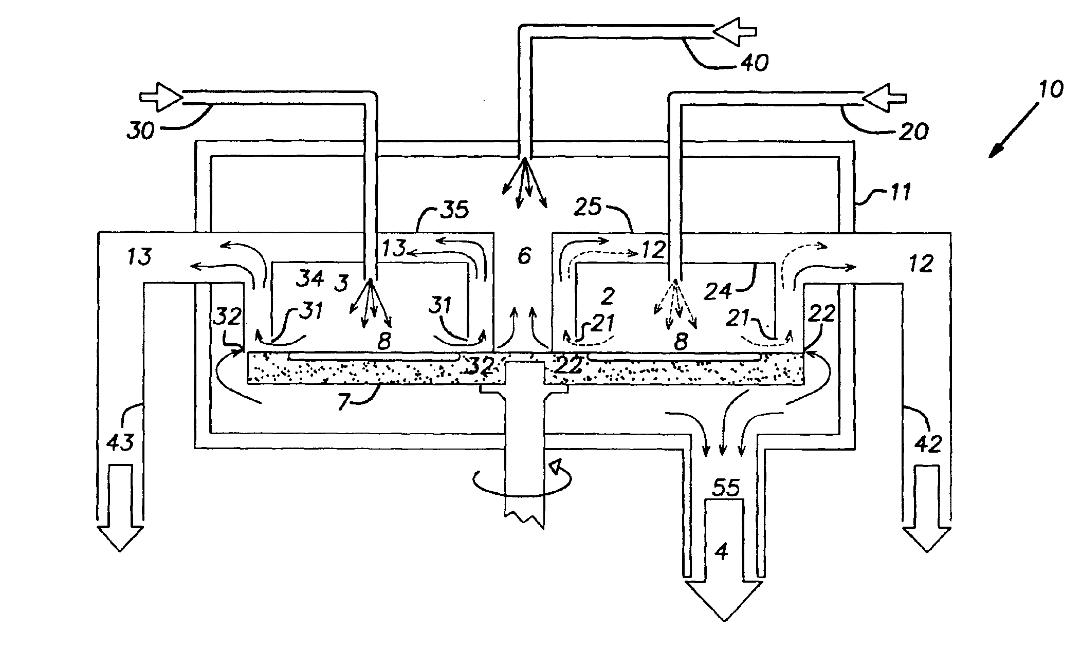
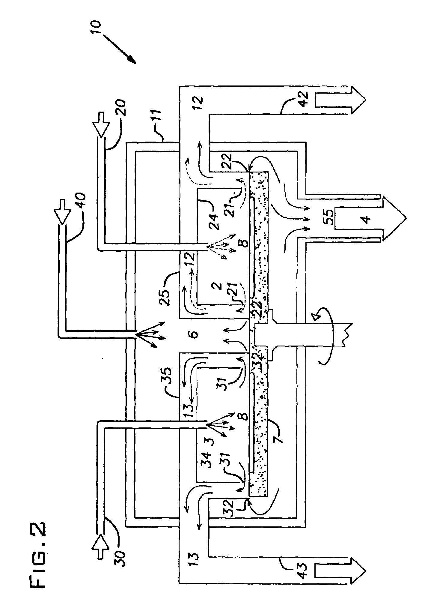
The present invention is designed to avoid intermixing of non-compatible gases in any place close to the substrate environment. Referring to FIG. 2, the apparatus 9 has an outer enclosure 11. The outer enclosure contains reactive enclosures 24 and 34 having reactive zones 2 and 3 that are supplied by reactive gas inlet pipes 20 and 30 respectively. A neutral gas inlet 40 supplies a neutral flush gas to the buffer zone 6 in the outer enclosure. A pipe 55 leads to a pump 4. The substrates 8 rest on the susceptor, a rotary turntable 7. The reactive enclosures 24 and 34 are surrounded by ring-shaped channels 25 and 35 respectively. The ring-shaped channels 25 and 35 are connected to separate exhaust pipes 42 and 43 respectively.

In operation, the turntable carries the substrates alt...


PUM

PropertyMeasurementUnit
Temperatureaaaaaaaaaa
Lengthaaaaaaaaaa
Fractionaaaaaaaaaa

Abstract

A chemical vapor deposition method and apparatus is disclosed. The process is carried out in an apparatus having a number reactive zones, each surrounded by a corresponding exhaust zone, all of which are both contained within a buffer zone. Pressure relationships are controlled such that buffer gas from the buffer zone flows into the exhaust zones and reactive gas from the reactive zones flow into the exhaust zones. As a result, cross-contamination of gases between the reactive zones is avoided.

Description

RELATED APPLICATION DATAThis application claims the benefit of U.S. Provisional Patent Application No. 60 / 394,086 filed Jul. 3, 2002, which is incorporated by reference herein in its entirety.FIELD OF THE INVENTIONThe invention relates to a method and apparatus for atomic layer deposition (ALD) or epitaxy, in particular a method for performing ALD using a rotary susceptor apparatus.BACKGROUND OF THE INVENTIONAtomic Layer Deposition (ALD) (also referred to as Atomic Layer Epitaxy, or ALE) is a Chemical Vapor Deposition (CVD) technique. Classical CVD is based on exposing a surface to a gas mixture. The surface is heated, and the heat induces a reaction and / or decomposition of the gases. This results in the formation of a solid film layer on the surface.ALE is a species of ALD and refers to the growth of a crystalline film on the substrate surface, while ALD is more general and extends to the deposition of amorphous materials as well. In this specification the term ALD will be generall...

Claims


Application Information

Patent Timeline
IPC IPC(8): C23C16/458C30B25/02C30B25/14C23C16/44C23C16/455
CPCC23C16/4412C23C16/45525C30B25/14C23C16/4584C30B25/02C23C16/45551
Inventor SCHMITT, JACQUES
Owner OERLIKON ADVANCED TECH
Why Eureka
Try Eureka