Catalytic oxidation process

a catalytic oxidation and reaction technology, applied in the direction of physical/chemical process catalysts, metal/metal-oxide/metal-hydroxide catalysts, bulk chemical production, etc., can solve the problems of high temperature generation, reactors, catalysts and other process equipment, and the gases formed in such a reaction are not directly useful for the production of valuable chemical compounds

Inactive Publication Date: 2002-09-10
EXXON RES & ENG CO
View PDF4 Cites 129 Cited by
  • Summary
  • Abstract
  • Description
  • Claims
  • Application Information

AI Technical Summary

Benefits of technology

A Rh metal coating was applied directly (using Rh nitrate solution in the absence of a washcoat) to a 0.75 inch (1.905 cm) diameter.times.0.5 inch (1.27 cm) long alumina foam body identified as Dycat brand 300 micron (nominally 65 ppi, manufactured by Dytech Corporation Limited, Sheffield, Great Britain) alumina foam carrier to obtain a Rh loading of 1.3 wt. % based on the total weight of the Rh plus alumina foam. This is referred to as sample "A".
A washcoated sample was prepared using procedures similar to those described for preparing the catalyst samples of

Problems solved by technology

The gases formed in such a reaction are not directly useful for the production of valuable chemical compounds.
Furthermore, if efforts were made to produce valuable products from water and carbon dioxide, the high temperatures generated would present problems with respect to reactors, catalysts and other process equipment.
Uneven flow distribution of the ammonia through the gauze pad (i.e., the catalyst bed) can result in an undesirable reaction that produces nitrogen and water; improvements in catalyst technology could improve such a commercially important process.
However, it is also stated that "lowering the O.sub.2 / CH.sub.4 ratio will make carbon deposition thermodynamically more favourable and thus lead to deactivation of the catalyst."

Method used


Image

  • Catalytic oxidation process
  • Catalytic oxidation process
  • Catalytic oxidation process

Examples


example 1

Catalyst R and Catalyst E were tested in a process for the catalytic partial oxidation of methane under the same conditions: the gas flow rate, expressed as gaseous hourly space velocity (GHSV, calculated as the flow rate of gases at "standard" temperature and pressure, i.e., 1 atm / 101.3 kPa and 68.degree. F. / 20.degree. C., divided by the total volume of the catalyst) in all runs was=144,207 / hr; pressure was 3.8-7.4 psig (0.126-0.150 MPa) and other conditions as noted in the table. All carbon balances closed between 98.9-99.8% (No other significant products were observed, i.e., none were present in amounts greater than 0.1 wt. %). A quartz reactor enclosed in a furnace was used to contain the catalyst. The furnace was used to control catalyst inlet temperature and minimize heat loss from the catalyst bed. Product gases, CO, CO.sub.2, H.sub.2, C.sub.2 H.sub.2, C.sub.2 H.sub.4, C.sub.2 H.sub.6, were quantified by GC (there was no detectable O.sub.2 in the product stream).

The table bel...

example 2

Scanning Electron Microscopy (SEM)

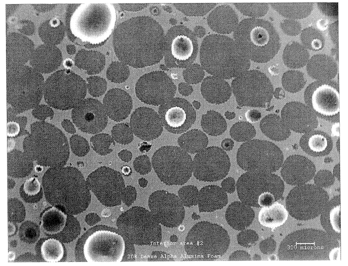
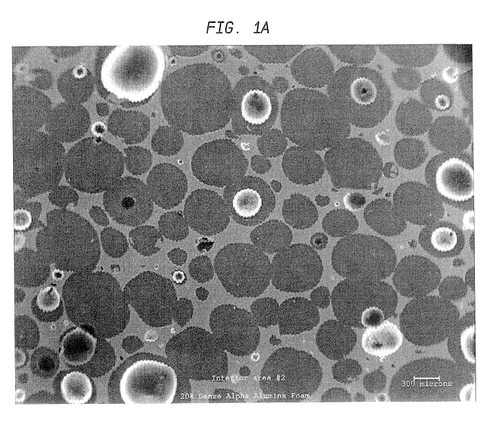
SEM was used to investigate the microstructure and uniformity of ceramic foams representative of those used to prepare Catalyst R and Catalyst E. Representative results are shown in FIGS. 1a and 1b. Each of these ceramic foam samples are identified as 65 ppi materials, but the sample of FIG. 1b is macroscopically more uniform. In addition, it contains very few of the smallest pore sizes, e.g., about 10 to about 40 microns (this is believed to result from a difference in the methods used to prepare the two materials).

The non-uniform sample of FIG. 1a also has an undesirable density gradient (for purposes of the present invention) having more foam material near the edges of the sample and an undesirable (also with regard to the present invention) low density of foam in the center of the sample. This is also believed to result from the method used to prepare the foam that is believed to involve a dip coating of alumina slip on an organic foam body. Suc...

example 3

X-Ray Microtomography (XMT)

In this example, X-ray microtomography was carried out on a catalyst sample similar to catalyst R, (the ceramic foam carrier starting material was obtained from the same source as that used for catalyst R, Hi-Tech Ceramics, Inc.) with the following differences:

(a) 45 vs. 65 ppi;

(b) washcoat loading=0.34 g / in..sup.3 (0.0207 g / cm.sup.3) vs. 0.24 g / in.sup.3 (0.0146 g / cm.sup.3); and

(c) sample size=0.5 in. diameter.times.0.5 in. long (1.27 cm..times.1.27 cm.) vs. 0.75 inch (1.905 cm) diameter.times.0.5 inch (1.27 cm) long

The density distribution of the ceramic foam carrier was measured at an x-ray energy of 23.3 keV. The concentration distribution of Rh was measured by subtracting the projections acquired at 23.3 keV (below the Rh K absorption edge) from projections acquired at 23.4 keV (above the Rh K absorption edge) and reconstructing the difference signal. The spatial resolution of the resulting 512.times.512.times.360 3D images is 11.54 microns / pixel. The ...


PUM


Abstract

A process for the partial catalytic oxidation of a hydrocarbon containing feed comprising contacting the feed with an oxygen-containing gas in the presence of a catalyst retained within a reaction zone in a fixed arrangement, wherein the catalyst comprises at least one catalytically active metal selected from the group consisting of silver and Group VIII elements supported on a porous ceramic carrier. The porous ceramic carrier has a distribution of total pores wherein about 70% of the total pores (1) have a volume-to-surface area (V/S) ration that is within about 20% of the mean V/S value for the total pores and no pores have a V/S ration that is greater than twice the mean V/S value for the total pores; (2) have a pore-to-pore distance between neighboring pores that is within about 25% of the mean pore-to-pore distance between neighboring pores; and (3) have a pore throat area that is within about 50% of the mean pore throat are for the pores. Additionally, about 50% of the total pores have a coordination number between neighboring pores that is within about 25% of the mean coordination number between neighboring pores. Preferably, the oxidation process comprises a multistage, staged oxygen, catalytic partial oxidation process having fewer than or equal to about five stages and including a first stage preheat temperature of greater than about 550° C., and wherein the temperature of the product mixture in each stage following the first stage is at least about 700° C.

Description

Process for the catalytic oxidation of hydrocarbons and other compounds utilizing ceramic foam supported catalysts. Included are processes for the preparation of carbon monoxide and hydrogen (certain mixtures of which are also known as synthesis gas or syngas) by catalytic partial oxidation (CPO) of low carbon number hydrocarbon feed streams, such as methane; catalytic oxidation of ethylene; catalytic oxidation of ammonia, etc. Syngas is useful for the preparation of a variety of other valuable chemical compounds, such as by application of the Fischer-Tropsch process; ethylene oxide and nitric acid also have significant commercially utility. Additionally, catalytic oxidation can be applied to processes for the reaction of hydrocarbon fuel with air and steam under conditions suitable for use in fuel cell reformer applications.1. Background of the InventionThe combustion of methane gas at elevated temperature, e.g., 1000.degree. F. (538.degree. C.) is highly exothermic and produces CO...

Claims


Application Information

Patent Timeline
Patent Type & Authority Patents(United States)
IPC IPC(8): B01J23/63B01J23/54B01J35/10B01J35/04B01J35/00C01B3/38C01B3/00C01B3/40B01J23/66B01J23/755B01J37/00B01J37/02B01J23/58
CPCB01J23/63B01J35/04B01J35/10C01B3/386C01B3/40B01J23/66B01J23/755B01J37/0207B01J37/0215C01B2203/0244C01B2203/0261C01B2203/0283C01B2203/066C01B2203/0844C01B2203/1017C01B2203/1023C01B2203/1047C01B2203/1052C01B2203/1064C01B2203/1082C01B2203/1241C01B2203/1247C01B2203/1276C01B2203/1288C01B2203/142C01B2203/82B01J35/1019Y02P20/52
Inventor FEELEY, JENNIFER SCHAEFERDUNSMUIR, JOHN HENRYREYES, SEBASTIAN CARMENBERLOWITZ, PAUL JOSEPHBRODY, JOHN FRANCESDERITES, BRUCE ANTHONYLAI, WENYIH FRANKTILLER, MARK LELANDWOO, HYUNG SUKBAI, CHUANSHENG
Owner EXXON RES & ENG CO
Why Eureka
Try Eureka