Magnetic material and manufacturing method thereof

a technology of magnetic materials and manufacturing methods, applied in the direction of magnetic materials, basic electric elements, magnetic bodies, etc., can solve the problems of reducing the uniformity of composition between particles, difficult grinding, and extremely low productivity of particles, and achieve the effect of increasing the manufacturing efficiency of magnetic materials having nazn13 crystal structure phas

Active Publication Date: 2006-11-16
KK TOSHIBA
View PDF8 Cites 33 Cited by
  • Summary
  • Abstract
  • Description
  • Claims
  • Application Information

AI Technical Summary

Benefits of technology

[0012] The present invention may provide a manufacturing method of a magnetic material in which a manufacturing efficiency of the magnetic material having NaZn13 crystal structure phase is increased, and characteristic

Problems solved by technology

Consequently, it is necessary to perform the heat treatment in high temperature and for a long time to obtain the LaFe13 based magnetic material from the integrated alloy.
Further, when a quenched material in a thin-band state or a spherical state is grinded to be used as a particulate magnetic refrigeration material, there is a problem that a uniformity of composition between particles is lowered because many α-Fe phases are contained.
In addition, the more there are the α-Fe phases, the more it becomes difficult to grind.
However, there is a problem that a compound phase containing B, for example, such as F2B phase exists as a hetero-phase in the alloy cast by this method, in accordance with an addition of B and so on to the raw

Method used


Image

  • Magnetic material and manufacturing method thereof
  • Magnetic material and manufacturing method thereof
  • Magnetic material and manufacturing method thereof

Examples


example 1

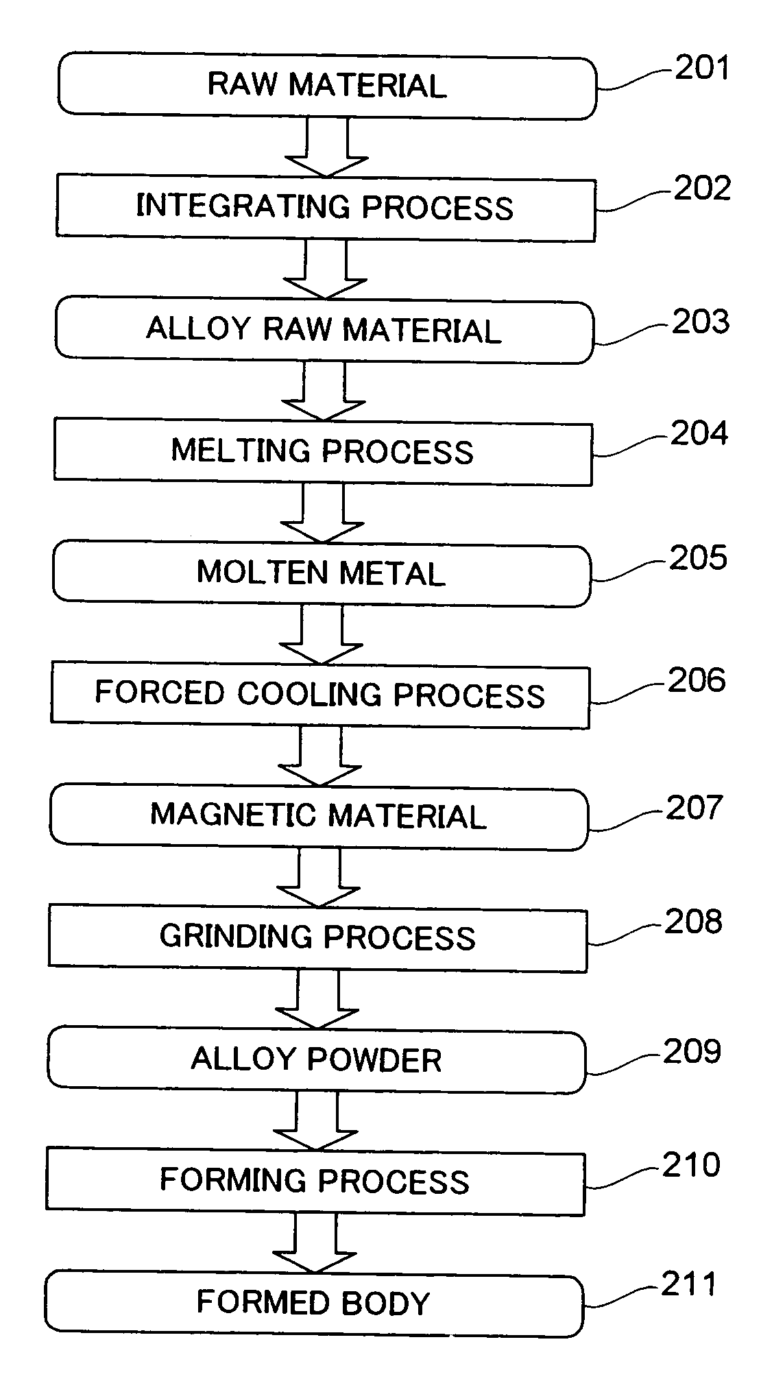
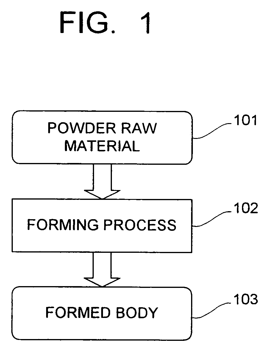
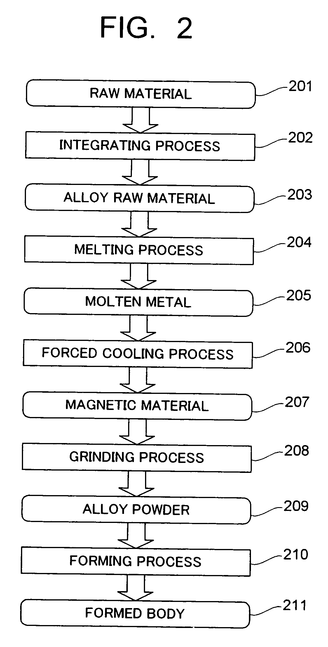
[0066] At first, LaSi powder with an average particle size of a 10 μm, Fe powder with the average particle size of a 6 μm, and Si powder with the average particle size of a 7 μm are prepared, and these are blended so as to be a stoichiometry of La(Fe0.88 Si0.12)13. Further, they are mixed and miniaturized so that the average particle size of the mixture becomes to be 5 μm. A composition ratio of respective elements within the mixed powder (powder raw material) is as follows: La is approximately 7.2 at.%; Fe is approximately 81.7 at.%; and Si is approximately 11.1 at.%.

[0067] Next, the miniaturized mixed powder (powder raw material) is sintered by using a pulse current pressure sintering equipment. The sintering is performed under a condition that a degree of vacuum within a chamber is 2 Pa, and a direct pulse current with a maximum voltage of 3.2 V, and a maximum current per pressure-receiving area of 500 A / cm2 is flowed while a sample is applied a pressure of 40 MPa. As a pulse co...

example 2

[0068] After the respective powders of LaSi, Fe, Co, Si are mixed to be La(Fe0.83Co0.05Si0.12)13, the pulse current pressure sintering is performed under the same condition with Example 1. The composition ratio of the respective elements within the mixture to be a raw material is as follows: La is approximately 7.2 at.%; Fe is approximately 77.1 at.%; Co is approximately 4.6 at.%; and Si is approximately 11.1 at.%.

example 3

[0069] After the respective powders of LaSi, Fe, Co, Si are mixed to be La(Fe0.88Co0.03Si0.09)13, the pulse current pressure sintering is performed under the same condition with Example 1. The composition ratio of the respective elements within the mixture to be the raw material is as follows: La is approximately 7.2 at.%; Fe is approximately 81.7 at.%; Co is approximately 2.8 at.%; and Si is approximately 8.3 at.%.

[0070] A powder X-ray diffraction is performed to investigate a constitutional phase of the sintered body of the magnetic material obtained as stated above. An X-ray diffraction result of the magnetic material according to Example 1 is shown in FIG. 3. As it is obvious from FIG. 3, the NaZn13 crystal structure phase is generated as a main phase, and a main peak intensity of the NaZn13 crystal structure phase is 3.34 times of the main peak intensity of the α-Fe phase.

[0071] A generation ratio of the NaZn13 crystal structure phase is asked from the powder X-ray diffractio...


PUM

PropertyMeasurementUnit
Particle sizeaaaaaaaaaa
Pressureaaaaaaaaaa

Abstract

A powder raw material is prepared by mixing at least two kinds of powders selected from a powder A, a powder B, a powder C, and a powder D. A sintered body of a magnetic material having an NaZn13 crystal structure phase is formed by heating the powder raw material while applying a pressure treatment. The powder A is at least one of elemental powder of element R selected from Y, La, Ce, Pr, Nd, Sm, Eu, Gd, Tb, Dy, Ho, Er, Tm, and Yb. The powder B is at least one of elemental powder of element T selected from Fe, Co, Ni, Mn, and Cr. The powder C is at least one of elemental powder of element M selected from Si, B, C, Ge, Al, Ga, and In. The powder D is a compound powder composed of at least two kinds of elements selected from the element R, the element T, and the element M.

Description

CROSS-REFERENCE TO THE INVENTION [0001] This application is based upon and claims the benefit of priority from the prior Japanese Patent Application No. 2005-141410, filed on May 13, 2005; the entire contents of which are incorporated herein by reference. BACKGROUND OF THE INVENTION [0002] 1. Field of the Invention [0003] The present invention relates to a manufacturing method of a magnetic material used for a magnetic refrigeration material, a magnetostrictive material, and so on, and to the magnetic material applying the method. [0004] 2. Description of the Related Art [0005] In recent years, as an environment-conscious refrigeration technique, an expectation for a magnetic refrigeration which is clean and has a high energy efficiency is increasing. On the other hand, as a magnetic material for the magnetic refrigeration, a substance in which a large magnetic entropy change can be obtained near a room temperature is found. As such a magnetic substance for the magnetic refrigeratio...

Claims


Application Information

Patent Timeline
IPC IPC(8): H01F1/08
CPCH01F1/015
Inventor TSUJI, HIDEYUKISAITO, AKIKOKOBAYASHI, TADAHIKO
Owner KK TOSHIBA
Why Eureka
Try Eureka