Electrical machine apparatus

a technology of electric machines and electrical equipment, applied in electrical equipment, mechanical energy handling, dynamo-electric machines, etc., can solve the problems of increasing the length of the coupling portion, limiting the maximum thrust per size of the electrical machine apparatus, and increasing the amount of windings, so as to facilitate the installation of the magnetic pole portion and facilitate the integration. , the effect of easy leakag

Active Publication Date: 2013-10-29
SANYO DENKI CO LTD
View PDF13 Cites 12 Cited by
  • Summary
  • Abstract
  • Description
  • Claims
  • Application Information

AI Technical Summary

Benefits of technology

[0004]An object of the present invention is to provide an electrical machine apparatus with an enhanced maximum thrust or maximum output per size of the electrical machine apparatus achieved by increasing the amount of windings without significantly increasing the magnetic resistance.
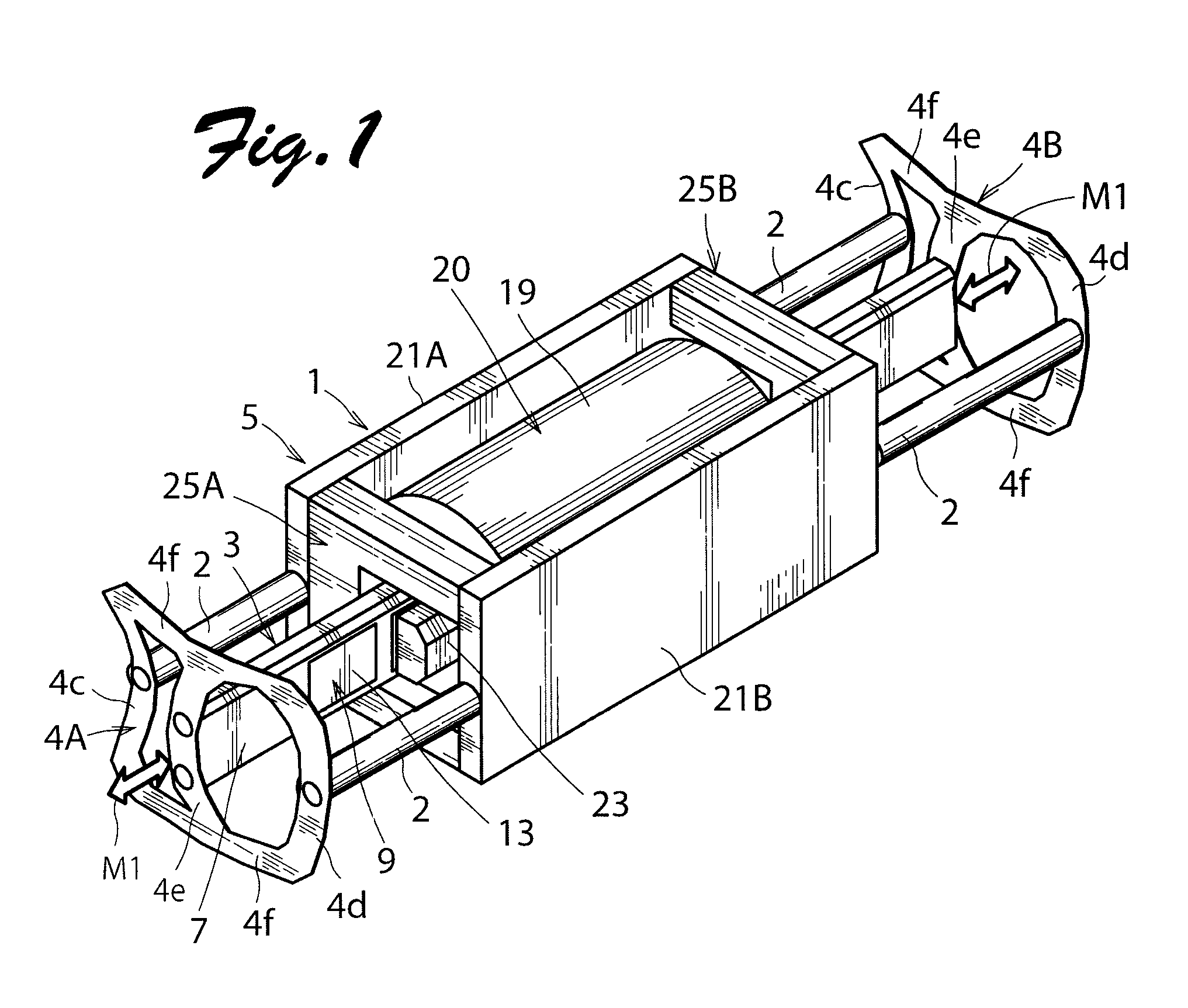
[0017]The first permanent magnet array and the second permanent magnet array may be mechanically coupled to each other, in which case one mover or stator is formed. With this configuration, the maximum thrust or the maximum output per size or for the size of the electrical machine apparatus may be doubled compared to when one permanent magnet array and one armature unit are provided. Alternatively, the first permanent magnet array and the second permanent magnet array may be disposed to be movable independently of each other, in which case components including the first and second permanent magnet arrays respectively serve as movers that vibrate in opposite directions. With this configuration, vibration of the mover including the first permanent magnet array and vibration of the mover including the second permanent magnet array cancel each other to reduce vibration of the entire electrical machine apparatus. Both the two movers may be connected to a load, or only one of the two movers may be connected to a load.

Problems solved by technology

In such an electrical machine apparatus as a linear actuator configured as described above, however, an increased amount of windings leads to increased length of the coupling portion, which tends to increase the magnetic resistance to cause magnetic saturation.
Therefore, when the electrical machine apparatus is a motor or an actuator, there is a limit to the maximum thrust per size of the electrical machine apparatus.
When the electrical machine apparatus is a generator, there is a limit to the maximum output per size of the electrical machine apparatus.

Method used


Image

  • Electrical machine apparatus
  • Electrical machine apparatus
  • Electrical machine apparatus

Examples


second embodiment

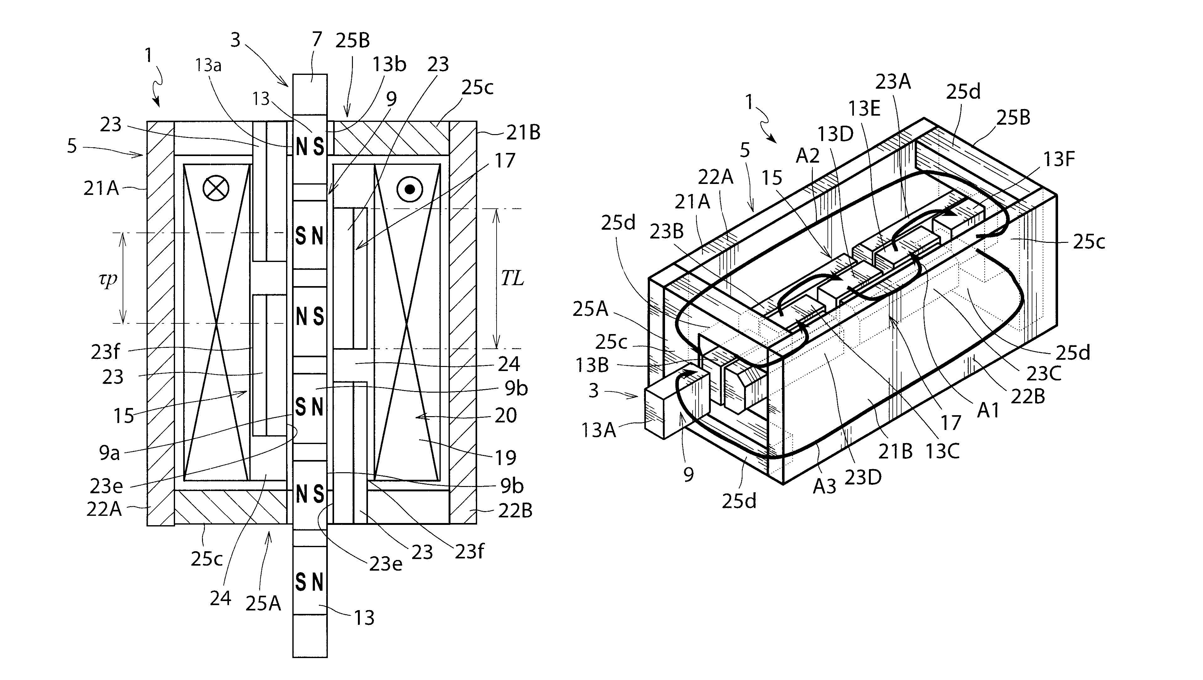
[0056]FIG. 5 is a perspective view schematically showing the internal structure of an electrical machine unit of an electrical machine apparatus according to the present invention. A mover support mechanism including the support member 2 and the first and second plate spring members 4A and 4B shown in FIG. 1 may also be used in the embodiments below. The electrical machine apparatus according to the embodiment has the same structure as the electrical machine apparatus shown in FIGS. 1 to 4 except for the structure of a pair of yoke members 121A and 121B. Therefore, components that are the same as those of the electrical machine apparatus shown in FIGS. 1 to 4 are denoted by reference numerals obtained by adding 100 to the reference numerals affixed to their counterparts in FIGS. 1 to 4 and their descriptions are omitted. Yoke bodies 122A and 122B of the yoke members 121A and 121B of the electrical machine apparatus according to the embodiment are disposed outside a winding 119 in th...

third embodiment

[0057]FIG. 6 is a perspective view schematically showing the internal structure of an electrical machine unit of an electrical machine apparatus according to the present invention. The electrical machine apparatus according to the embodiment has the same structure as the electrical machine apparatus shown in FIGS. 1 to 4 except for a yoke member. Therefore, components that are the same as those of the electrical machine apparatus shown in FIGS. 1 to 4 are denoted by reference numerals obtained by adding 200 to the reference numerals affixed to their counterparts in FIGS. 1 to 4 and their descriptions are omitted. In a yoke member 221 of the electrical machine apparatus according to the embodiment, a yoke body 222 is disposed only on one outer side of a winding 219 in the radial direction of the winding 219 in a direction perpendicular to the direction in which a first magnetic pole portion assembly 215, a permanent magnet array 209, and a second magnetic pole portion assembly 217 fa...

fourth embodiment

[0058]FIGS. 7 and 8 are respectively a perspective view and a cross-sectional view schematically showing the internal structure of an electrical machine unit of an electrical machine apparatus according to the present invention. The electrical machine apparatus according to the embodiment has the same structure as the electrical machine apparatus shown in FIGS. 1 to 4 except for the number of magnetic pole portions and a yoke member. Therefore, components that are the same as those of the electrical machine apparatus shown in FIGS. 1 to 4 are denoted by reference numerals obtained by adding 300 to the reference numerals affixed to their counterparts in FIGS. 1 to 4 and their descriptions are omitted. In the electrical machine apparatus according to the embodiment, a first magnetic pole portion assembly 315 includes two magnetic pole portions 323. A second magnetic pole portion assembly 317 includes three magnetic pole portions 323.

[0059]In a yoke member 321 of the electrical machine...


PUM


Abstract

A mover includes a permanent magnet array including permanent magnets magnetized in a perpendicular direction perpendicular to a motion direction of the mover such that magnetic poles having different polarities alternately appear on magnetic pole surfaces of the permanent magnets along the motion direction. A stator includes first and second magnetic pole portion assemblies disposed on both sides of the permanent magnet array in the perpendicular direction and each including magnetic pole portions facing the magnetic pole surfaces, and a single phase winding that excites the magnetic pole portions forming the first and second magnetic pole portion assemblies. The winding has a hollow structure formed by winding a winding conductor into a coil such that the magnetic pole portions included in the first magnetic pole portion assembly and the magnetic pole portions included in the second magnetic pole portion assembly are located in an internal space of the winding.

Description

TECHNICAL FIELD[0001]The present invention relates to an electrical machine apparatus such as an actuator, a motor, and a generator with an increased amount of windings.BACKGROUND ART[0002]Japanese Patent Application Publication No. 2006-320150 (JP2006-320150A) discloses a linear actuator (an electrical machine apparatus) including a stator and a mover that reciprocates with respect to the stator to generate vibration. The mover includes a pair of permanent magnet arrays each including a plurality of permanent magnets arranged in an array in a motion direction in which the mover reciprocates. The stator includes an armature including a stator core and an excitation winding. The stator core includes first and second magnetic pole portions facing magnetic pole surfaces of the plurality of permanent magnets, and a yoke portion coupled to the first and second magnetic pole portions via a coupling portion. The yoke portion is disposed outside the excitation winding in the radial directio...

Claims


Application Information

Patent Timeline
Patent Type & Authority Patents(United States)
IPC IPC(8): H02K33/16
CPCH02K33/16H02K41/031H02K1/145H02K7/08H02K16/00H02K2207/03H02K2201/12H02K2213/03
Inventor SUGITA, SATOSHIMISAWA, YASUSHITANG, YUQI
Owner SANYO DENKI CO LTD
Why Eureka
Try Eureka