Spiral heat exchanger

a heat exchanger and spiral technology, applied in indirect heat exchangers, laminated elements, lighting and heating apparatus, etc., can solve the problems that the suggested attempts to improve the heat transfer of spiral heat exchangers fully succeed in providing a good solution, and achieve the effect of improving heat transfer and strength

Inactive Publication Date: 2013-11-05
ALFA LAVAL CORP AB
View PDF27 Cites 19 Cited by
  • Summary
  • Abstract
  • Description
  • Claims
  • Application Information

AI Technical Summary

Benefits of technology

[0018]Another object of the present invention is to provide a spiral heat exchanger having improved heat transfer characteristics and improved mechanical strength.
[0021]A spiral heat exchanger with a heat transfer surface provided with corrugations or corrugated pattern fields gives improved strength and improved heat transfer compared with the traditional flat heat transfer surface of a spiral heat exchanger. The actual heat transfer surface becomes also larger compared with a conventional spiral heat exchanger of the same size.

Problems solved by technology

None of the above suggested attempts to improve the heat transfer of a spiral heat exchanger fully succeeds in providing a good solution, since they are either too complicated in their construction or merely tries to copy features of plate heat exchangers into the spiral heat exchangers without adapting them to the characteristics of the spiral heat exchanger.

Method used


Image

  • Spiral heat exchanger
  • Spiral heat exchanger
  • Spiral heat exchanger

Examples


Embodiment Construction

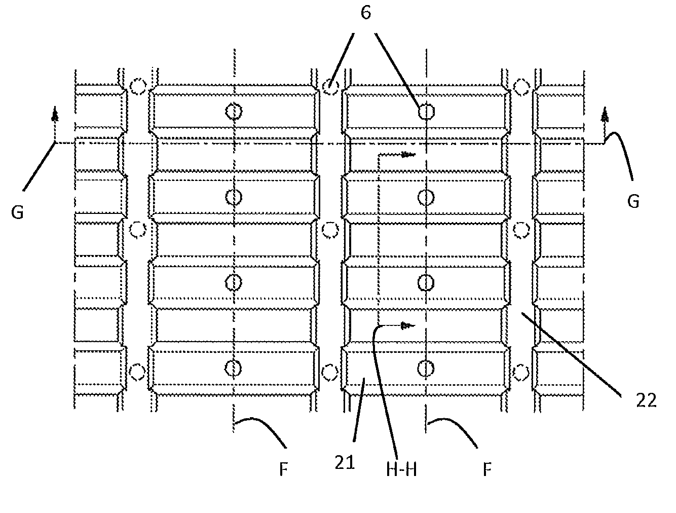
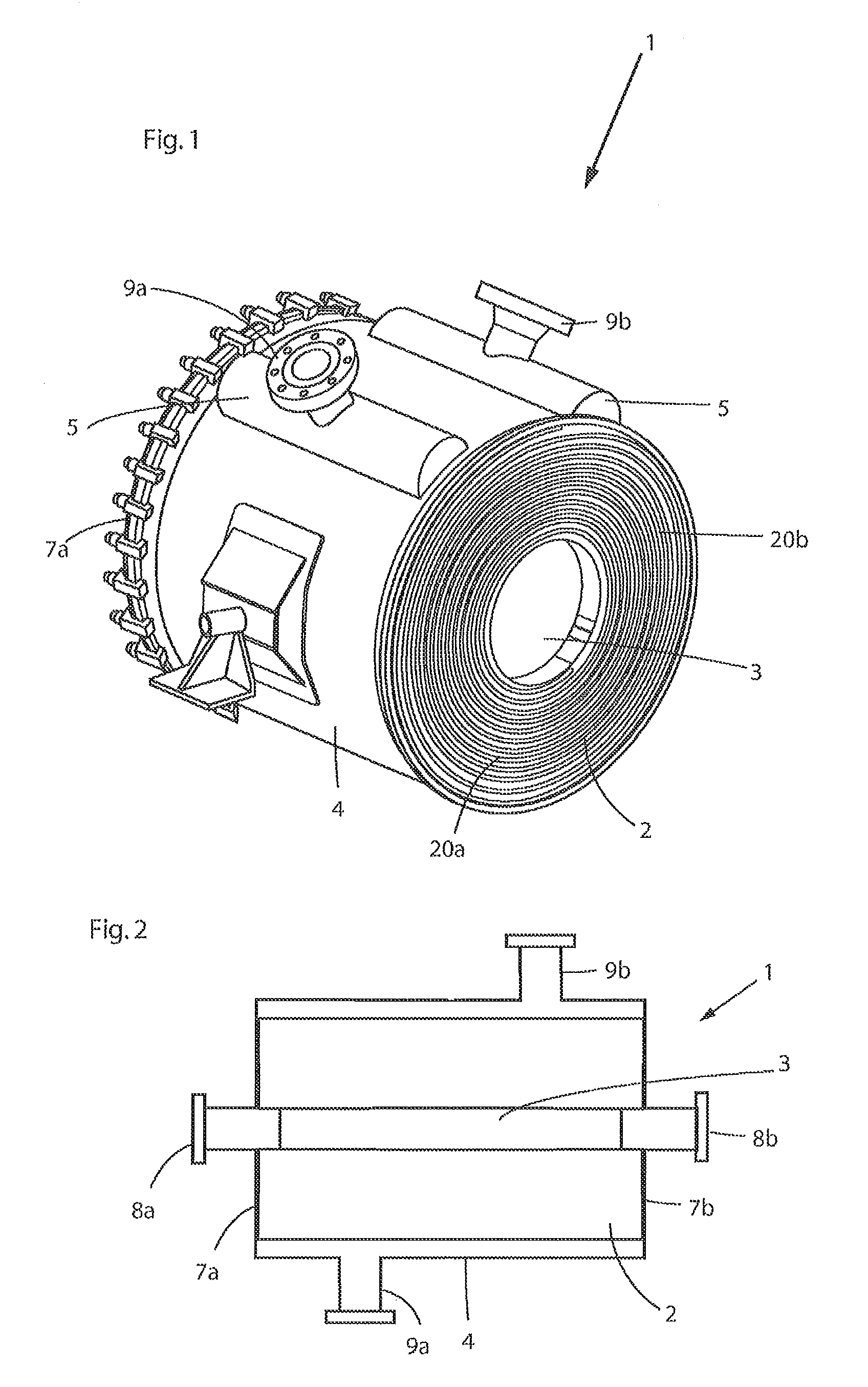
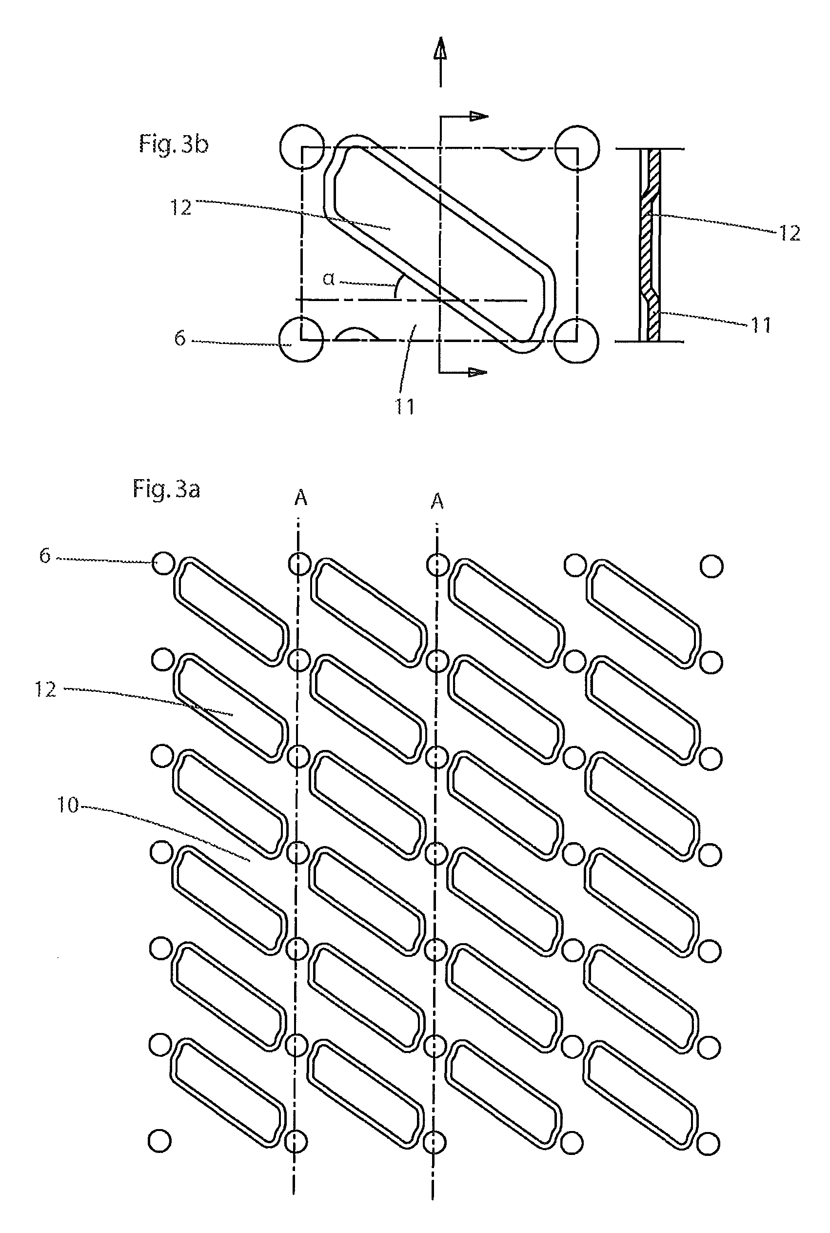
[0027]A spiral heat exchanger 1 includes at least one spiral sheet extending along a respective spiral-shaped path around a common centre axis and forming at least two spiral-shaped flow channels 20a, 20b, which flow channels 20a, 20b are substantially parallel to each other. Each flow channel includes a radially outer orifice, which enables communication between the respective flow channel and a respective outlet / inlet conduit and which is located at a radially outer part of the respective flow channel with respect to the centre axis, and a radially inner orifice, which enables communication between the respective flow channel and a respective inlet / outlet chamber, so that each flow channel permits a heat exchange fluid to flow in a substantially tangential direction with respect to the centre axis. The centre axis extends through the inlet / outlet chambers at the radially inner orifice. Distance members (not shown in FIG. 1), having a height corresponding to the width of the flow c...


PUM


Abstract

A spiral heat exchanger includes a spiral body formed by at least one spiral sheet wound to form the spiral body forming at least a first spiral-shaped flow channel for a first medium and a second spiral-shaped flow channel for a second medium, wherein the spiral body is enclosed by a substantially cylindrical shell being provided with connecting elements communicating with the first flow channel and the second flow channel, where the at least one spiral sheet comprises a corrugated heat transfer surface with corrugations for increasing the heat transfer and supports for spacing the wounds of the at least one spiral sheet in the spiral body.

Description

[0001]The present invention refers generally to spiral heat exchangers allowing a heat transfer between two fluids at different temperature for various purposes. Specifically, the invention relates to a spiral heat exchanger having a corrugated heat transfer surface.BACKGROUND OF INVENTION[0002]Conventionally, spiral heat exchangers are manufactured by means of a winding operation. The two flat sheets are welded together at a respective end, wherein the welded joint will be comprised in a center portion of the sheets. The two sheets are wound around one another to form the spiral element of the sheets so as to delimit two separate passages or flow channels. Distance members, having a height corresponding to the width of the flow channels, are attached to the sheets.[0003]Two inlet / outlet channels are formed in the center of the spiral element. The two channels are separated from each other by the center portion of the sheets. A shell is welded onto the outer periphery of the spiral ...

Claims


Application Information

Patent Timeline
Patent Type & Authority Patents(United States)
IPC IPC(8): F28D7/02F28F3/00
CPCF28D9/04F28F3/046
Inventor BLOMGREN, RALF
Owner ALFA LAVAL CORP AB
Why Eureka
Try Eureka