Remote manipulator for manipulating live multiple sub-conductors in a single phase bundle

a multi-conductor, multi-phase technology, applied in the direction of machine supports, applications, special-purpose vessels, etc., can solve the problems of requiring the de-energizing of a portion, affecting the service life of hot lines, and requiring a portion de-energizing, etc., to achieve the effect of increasing the surge impedance load, reducing phase spacing, and increasing bundle spacing

Active Publication Date: 2013-11-05
QUANTA ASSOC
View PDF10 Cites 7 Cited by
  • Summary
  • Abstract
  • Description
  • Claims
  • Application Information

AI Technical Summary

Benefits of technology

[0012]It has now been found to be desirable in some circumstances, and it is an object of the present invention, to provide or attain higher surge impedance loading (SIL) on overhead lines. To accomplish this it is advantageous to increase bundle spacing. It may also be advantageous to decrease phase spacing. It is also been proven that on two bundle lines, tipping the bundle (adjusting the height of the sub-conductors so that they are not at the same elevation) lowers the chances of line galloping or vibration, thus reducing conductor damage.
[0015]Increasing the bundle spacing may involve mainly hardware modifications to the line material that attaches the conductor to the insulator. An example of a group of lines which may benefit from improved SIL performance includes a typical turn conductor configuration in a horizontal arrangement spaced apart by a typical distance of 380 mm (15 inches) apart by a yoke plate. Two examples for improving the spacing between the sub-conductors of a phase include, firstly, dropping one conductor by introducing an extension link between the yoke plate and the suspension clamp to space the conductors apart, for example, 700 mm (23 inches). The other example involves a bigger yoke plate to space the conductors apart horizontally a distance of, for example, 700 mm. The present invention assists in achieving an increased somewhat optimized spacing between conductors for improved SIL performance.
[0028]f) separating from each other by an optimized separation distance distal ends of the each insulator, so as to improve the surge impedance loading of the single phase bundle by separation of the corresponding distal ends by the optimized separation distance.

Problems solved by technology

Hot line repair work is a potentially hazardous undertaking.
Conventional fiberglass insulated tools are limited to use only in good weather.
However, where a structures supports vertically separated energized lines, wind gusts and rotor downwash make this practice difficult and may require the de-energizing of a portion of the electrical transmission line.

Method used


Image

  • Remote manipulator for manipulating live multiple sub-conductors in a single phase bundle
  • Remote manipulator for manipulating live multiple sub-conductors in a single phase bundle
  • Remote manipulator for manipulating live multiple sub-conductors in a single phase bundle

Examples


Embodiment Construction

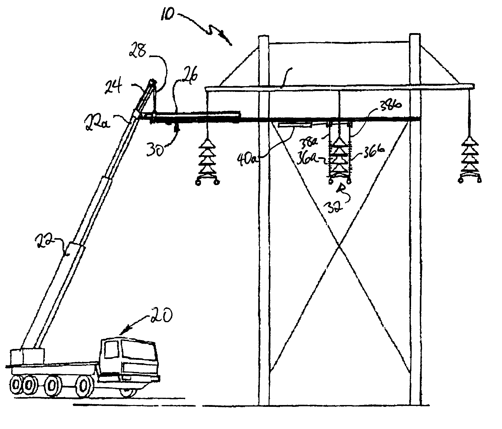
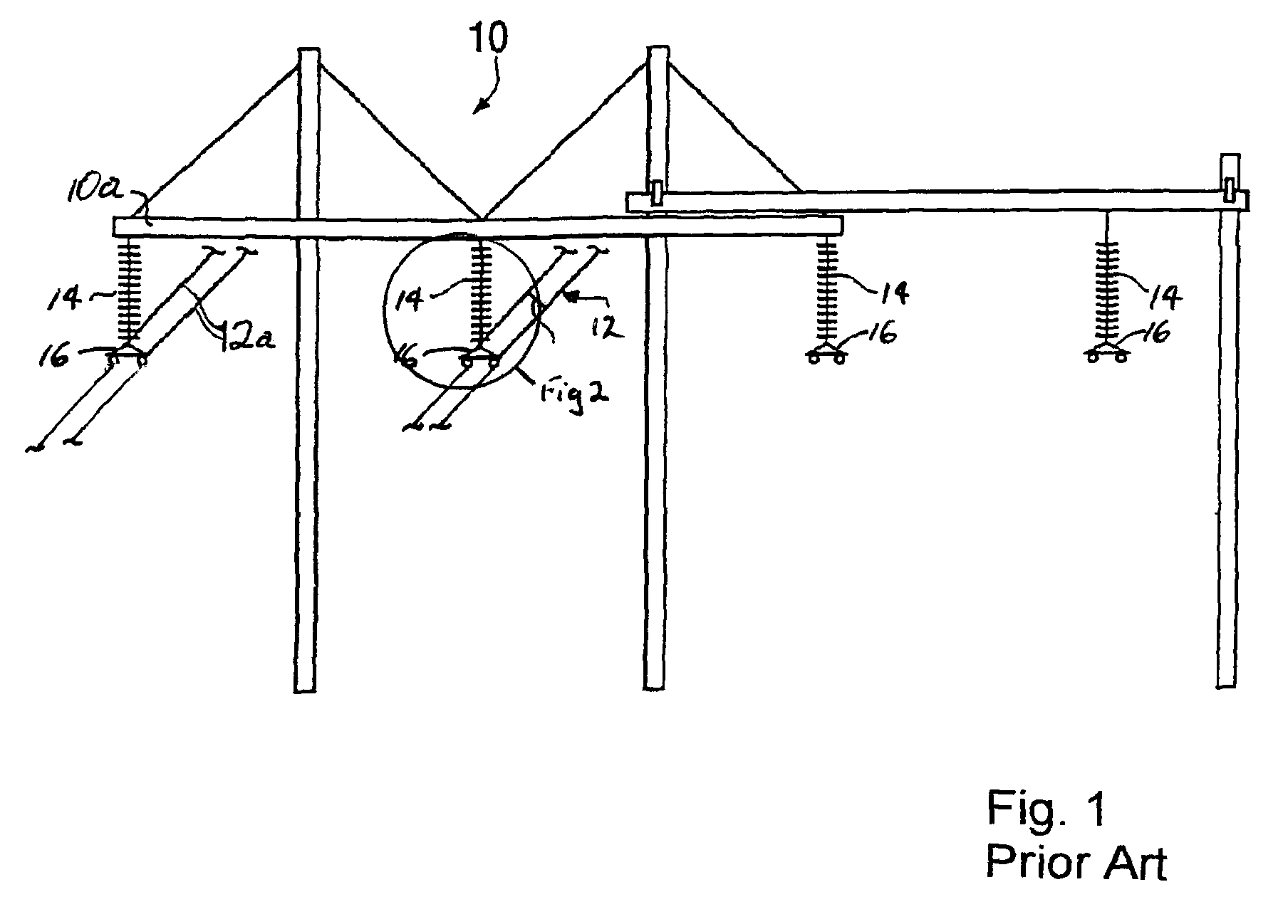
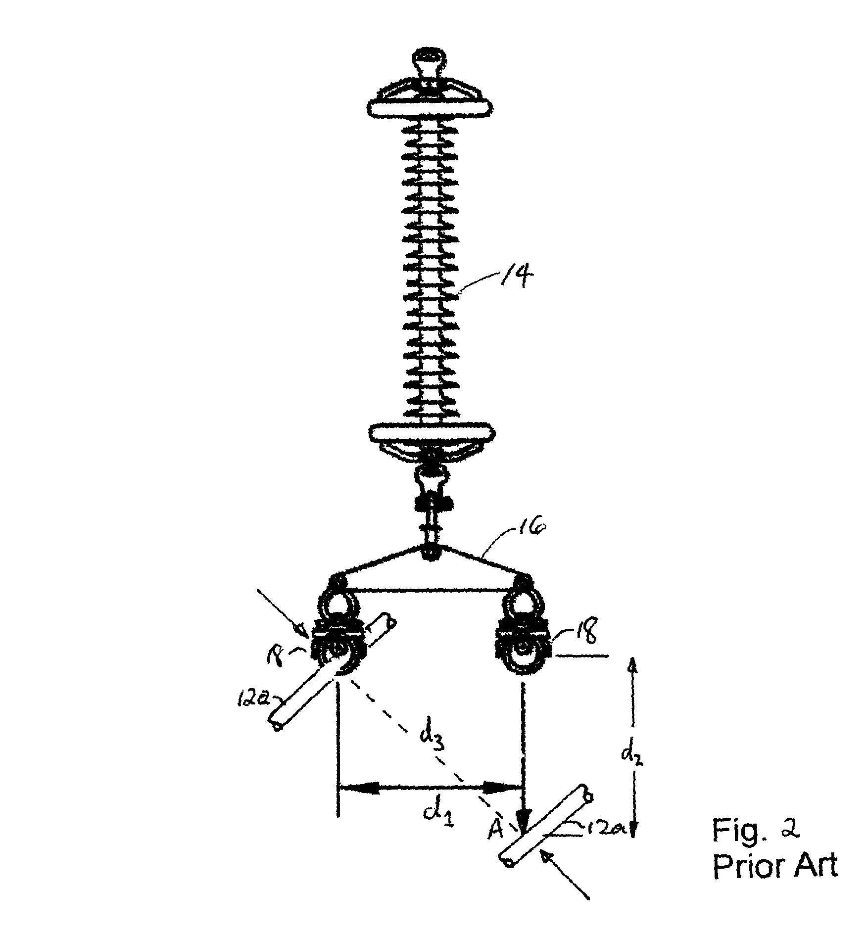
[0057]In the accompanying drawing figures, similar characters of reference denote corresponding parts in each view. As shown in the prior art, it is known in the prior art to suspend from structures 10 energized, that is, electrically live, overhead transmission lines 12 by means of conventional insulators 14 suspended so as to depend downwardly from the cross arms of the towers. Often, within a single phase bundle, the single phase will be carried by multiple sub-conductors 12a. Conventionally, a pair of such sub-conductors 12a will be supported from a cross arm 10a by yoke plate 16, better seen in FIG. 2, itself suspended by a insulator(s) 14.

[0058]The capacity of the single phase bundle may be improved if the surge impedance loading can also be improved. The surge impedance loading can be improved by increasing the spacing between sub-conductors 12a, for example, increasing the separation distance d1 between sub-conductors 12a suspended by couplings such as suspension clamps 18 f...


PUM


Abstract

A manipulator for separating sub-conductors in an energized single phase bundle includes a rigid support member and first and second actuators mounted on the support member, wherein each actuator is independently actuable of the other. Insulators are mounted on each actuator. A selectively releasable coupler is mounted on each insulator for selectively releasable coupling of each insulator to a corresponding sub-conductor. The actuators extend corresponding insulators independently of one another from the support member to thereby separate from each other by an optimized separation distance the distal ends of each insulator. When the corresponding sub-conductors of the single phase bundle are releasably coupled to the corresponding distal ends of the insulators the surge impedance loading of the single phase bundle may be improved by separation of the corresponding distal ends of the insulators and the sub-conductors by the optimized separation distance.

Description

FIELD OF THE INVENTION[0001]This invention relates to a device which is attached to the boom of a crane or similar device, and the corresponding method for the precise and remote manipulation of live sub-conductors in a single phase bundle of an energized overhead high voltage transmission line.BACKGROUND OF THE INVENTION[0002]As we describe in our U.S. Pat. No. 5,538,207, which issued Jul. 23, 1996 for our Boom-Mountable Robotic Arm, high voltage transmission and distribution lines are typically strung between a series of spaced-apart support structures or poles. The conductors are connected to insulators mounted on or suspended from cross arms extending at the upper end of transmission or distribution poles, or conductor support points built into transmission structures. Periodically it is necessary to replace or repair the poles or structures, cross arms and insulators to maintain the electrical circuit in good working order. It is preferable if this maintenance and repair work c...

Claims


Application Information

Patent Timeline
Patent Type & Authority Patents(United States)
IPC IPC(8): B66F3/00E21C29/16B63B35/03B65H59/00F16L3/00H02G1/08H02G7/12F16M13/00H02G1/02
CPCH02G1/02B66C23/66B66C23/68B66C1/42H02G1/04
Inventor DEVINE, CLIFFORD WILLIAMO'CONNELL, DANIEL NEIL
Owner QUANTA ASSOC
Why Eureka
Try Eureka