Supercharge Your Innovation With Domain-Expert AI Agents!

Control unit and method to operate a vehicle

a technology of control unit and control unit, which is applied in the direction of vehicle sub-unit features, mechanical equipment, transportation and packaging, etc., can solve the problems of damage to the form-locking shift element, and achieve the effect of reducing torque, avoiding damage to and safely closing the form-locking shift elemen

Active Publication Date: 2013-11-05
ZF FRIEDRICHSHAFEN AG
View PDF13 Cites 0 Cited by
  • Summary
  • Abstract
  • Description
  • Claims
  • Application Information

AI Technical Summary

Benefits of technology

[0008]Therefore, if the control unit determines that the output-side rotational speed gradient of the form-locking shift element drops too much after the form-locking shift element is activated in order to close the form-locking shift element, for example due to braking intervention by the driver or load withdrawal by the driver at the accelerator pedal or gas pedal of the motor vehicle, torque is actively built up at the drive assembly in order to ensure the defined rotational speed difference between the output-side component and the input-side component of the form-locking shift element for closing the form-locking shift element. Thus damage to the form-locking shift element while the form-locking shift element closes can be avoided.
[0009]According to an advantageous development of the invention, if the control unit determines that the monitored output-side rotational speed gradient exceeds an upper limit, the control unit generates a control signal for the drive assembly in order to reduce the torque at the drive assembly. Therefore, if the control unit determines that the monitored rotational speed gradient of the form-locking shift element becomes too large, for example as the result of a load build up by the driver at the accelerator pedal or gas pedal of the motor vehicle, the control unit actively limits the torque of the drive assembly to ensure that the defined rotational speed difference between the input-side component and the output-side component of the shift element is present during the closing of the form-locking shift element. The purpose of this is again to safely close the form-locking shift element while avoiding damage to the form-locking shift element.

Problems solved by technology

In contrast, greater rotational speed differences can cause damage to the form-locking shift element.

Method used


Image

  • Control unit and method to operate a vehicle
  • Control unit and method to operate a vehicle

Examples


Embodiment Construction

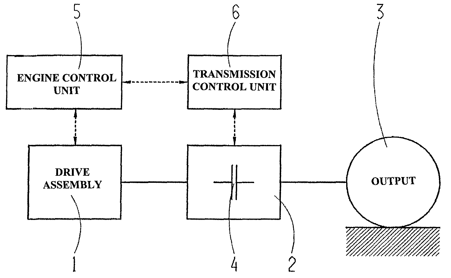
[0015]FIG. 1 shows a highly schematized drive train diagram of a motor vehicle. According to FIG. 1, the motor vehicle has a drive assembly 1, a transmission 2, and an output 3, wherein the transmission 2 is connected between the drive assembly 1 and the output 3.

[0016]The transmission 2 comprises at least one form-locking shift element 4, which can be designed for example as a claw and which has an input-side component and an output-side component.

[0017]FIG. 1 also shows an engine control unit 5 for controlling the operation of the drive assembly 1 in an open-loop or closed-loop manner and a transmission control unit 6 for controlling the operation of the transmission 2 in an open-loop or closed-loop manner. The engine control unit 5 exchanges data with the drive assembly 1 according to the double arrow. Likewise, the transmission control unit 6 exchanges data with the transmission 2. Furthermore, data is exchanged between the engine control unit 5 and the transmission control unit...


PUM


Abstract

A control unit of a motor vehicle for activating a form-locking shift element of a transmission of the motor vehicle in such a way that a defined rotational speed difference is defined, between an input-side component of the form-locking shift element and an output-side component of the form-locking shift element, in order to engage the form-locking shift element. The control unit monitors the rotational speed gradient of the rotational speed of the output-side component of the form-locking shift element from an activation time of the form-locking shift element, at which the engagement process of the form-locking shift element begins. The control unit generates a control signal for a drive assembly in order to increase the torque, at a drive assembly, in the event that the control unit determines that the monitored rotational speed gradient falls below a lower limit.

Description

[0001]This application claims priority from German patent application serial no. 10 2011 081 005.6 filed Aug. 16, 2011.FIELD OF THE INVENTION[0002]The invention relates to a control unit of a motor vehicle and a method for operating a motor vehicle.BACKGROUND OF THE INVENTION[0003]Motor vehicles with transmissions that have form-locking shift elements and / or friction-locking shift elements are known from the practice. For friction-locking shift elements, there can be a relatively large rotational speed difference between an input-side component and an output-side component of a friction-locking shift element when the friction-locking shift element closes, wherein this rotational speed difference can be reduced by friction power at the friction-locking shift element. In contrast, the closing of a form-locking shift element requires that a defined, relatively low rotational speed difference be met between an input-side component and an output-side component of the form-locking shift e...

Claims


Application Information

Patent Timeline
Patent Type & Authority Patents(United States)
IPC IPC(8): B60W10/04
CPCB60W30/19F16H61/04F16H63/502B60W2710/0666B60Y2400/421F16H2061/0474
Inventor WELLER, JENS
Owner ZF FRIEDRICHSHAFEN AG
Features
  • R&D
  • Intellectual Property
  • Life Sciences
  • Materials
  • Tech Scout
  • Unparalleled Data Quality
  • Higher Quality Content
  • 60% Fewer Hallucinations
Learn More