
Method for operating a network having a ring topology

a technology of ring topology and network, applied in the direction of transmission, transmission system, programme control, etc., can solve the problems of null data transmission, hindering its use, and inability to guarantee the uninterrupted connection between the stations over time, etc., to achieve convenient maintenance, convenient use, and economic benefits.

Inactive Publication Date: 2013-11-05
BOSCH REXROTH AG
View PDF16 Cites 0 Cited by
  • Summary
  • Abstract
  • Description
  • Claims
  • Application Information

AI Technical Summary

Benefits of technology

[0021]In the method according to the present invention, the physical connection between two stations advantageously corresponds to an Ethernet standard using electrical data routing. In principle, the Ethernet standard supports not only electrical data routing, but also optical data routing via optical waveguides. The advantageous use of an Ethernet standard using electrical data routing, for example according to the IEEE 802.3 standard, in a network having a ring topology, in particular in a time-critical environment, makes it possible to use tried and tested components that are economical to provide and easy to maintain. Of course, an Ethernet standard using optical data routing may also be used.
[0022]In the method according to the present invention, it is advantageous to use the false carrier indication signal for monitoring the carrier signal. This signal is provided by Ethernet interface circuits, which makes it easy to use. The use of this signal enables a faulty connection to be detected within just a few hundred nanoseconds.
[0023]The method according to the present invention is advantageously used in a network having a contradirectional dual-ring structure in which each station has one input interface and one output interface for each ring. By using a dual-ring structure, it is possible to maintain network operation by appropriately rerouting the data even if one connecting path fails. A network whose stations are able to reroute data in this manner is known as a self-healing network.
[0025]In another exemplary embodiment, with the method according to the present invention, if, after a faulty connection is detected, the station may route the data from its own output interface, which is connected to the input interface of a second station, to its own input interface, which is connected in a faulty manner to the output interface of the second station. This advantageous routing of data after detecting a faulty connection enables network operation, e.g., in a dual-ring network, to be easily maintained.
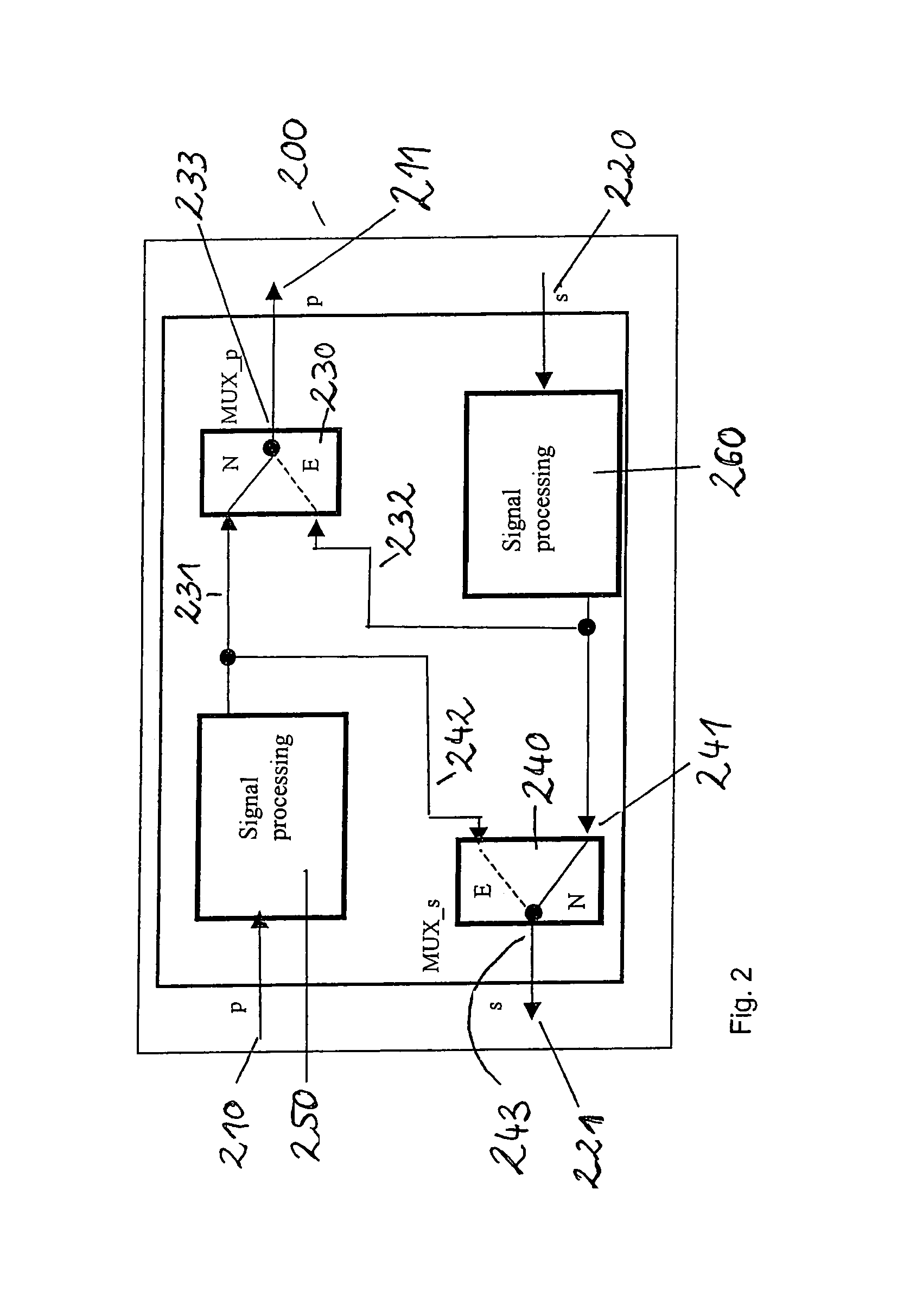
[0029]In another exemplary embodiment, the exemplary device according to the present invention includes two input interfaces, two output interfaces and two multiplexer circuits which connect the input interfaces to the output interfaces in such a way that, during error-free operation, each input interface is connected to a corresponding output interface and, upon detection of a faulty connection at one input interface, the corresponding output interface is connected to the other input interface. This exemplary embodiment is easy and economical to produce.

Problems solved by technology

However, a connection between the stations which remains uninterrupted over time can never be guaranteed, since problems may always occur within the connection, e.g., cable ruptures and the like.
Nevertheless, null data is transmitted to continuously check whether this ring is free of errors.
The above-discussed method may require a great deal of time to detect and subsequently eliminate a fault, which may hinder its use in systems which require a nearly uninterrupted connection, such as industrial manufacturing systems.
Glass fibers are highly sensitive in their handling and require complex connecting techniques.
In addition, the use of OWG technology increases the cost of providing and maintaining the transmission medium itself as well as plugs, network cards, etc.

Method used


Image

  • Method for operating a network having a ring topology
  • Method for operating a network having a ring topology
  • Method for operating a network having a ring topology

Examples


Embodiment Construction

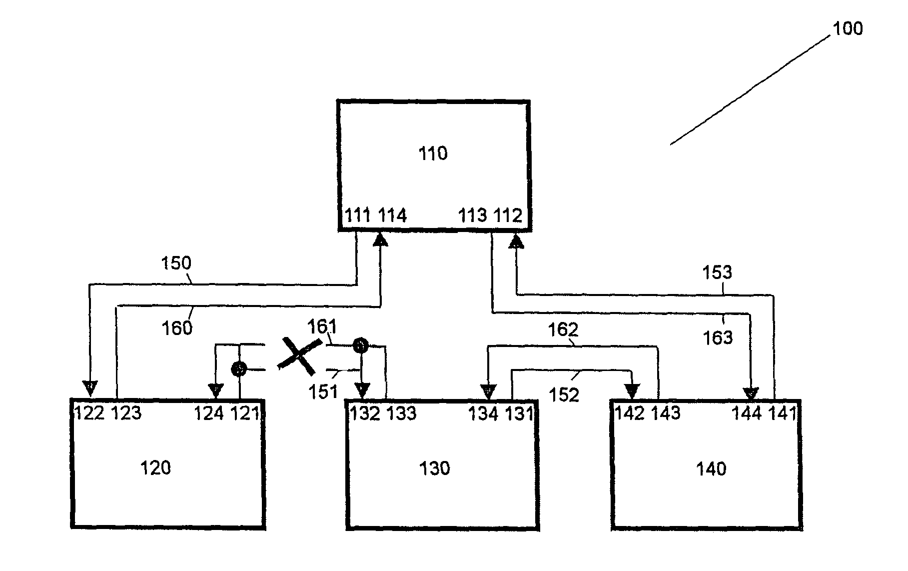
[0033]In FIG. 1, a network having a ring topology is identified as a whole by reference numeral 100. Network 100 includes four stations 110, 120, 130, 140, a primary ring 150, 151, 152, 153 and a secondary ring 160, 161, 162, 163. Each station 110, 120, 130, 140 has one output interface 111, 121, 131, 141 and one input interface 112, 122, 132, 142 for primary ring 150, 151, 152, 153. Each station 110, 120, 130, 140 also has one output interface 113, 123, 133, 143 and one input interface 114, 124, 134, 144 for secondary ring 160, 161, 162, 163.

[0034]In this manner, each station is connected to an adjacent station via two ring connecting sections, via one input interface and one output interface. For example, station 110 is connected to station 120 via primary ring section 150 from output interface 111 of station 110 to input interface 122 of station 120.

[0035]The two stations 110, 120 are also connected via ring section 160 of the secondary ring via interfaces 123 and 114.

[0036]In th...


PUM


Abstract

A method for operating a network having a ring topology, in which a faulty connection between two stations of the network is detected by monitoring carrier signals. This method enables a faulty connection to be quickly detected in a network. Data may be advantageously rerouted in response to the detection.

Description

FIELD OF THE INVENTION[0001]The present invention relates to a method for operating a network having a ring topology, a device for carrying out this method, and a corresponding network.BACKGROUND INFORMATION[0002]The importance of networks or network services has risen steadily in recent years. In addition to their generally known use as a communication platform, e.g., the Internet, the use of networks in industrial environments is also growing in importance, e.g., in networked control and automation systems.[0003]In industrial applications, in particular, an error-free, continuously available network connection between the individual stations is important to avoid production problems or even outages.[0004]However, a connection between the stations which remains uninterrupted over time can never be guaranteed, since problems may always occur within the connection, e.g., cable ruptures and the like.[0005]In network technology, therefore, a number of methods exists for detecting conne...

Claims


Application Information

Patent Timeline
Patent Type & Authority Patents(United States)
IPC IPC(8): H04J3/06H04L69/40
CPCH04L12/423H04L41/0668G05B2219/31137H04L2012/5627Y04S40/166Y04S40/00
Inventor GROSS, ALEXANDERPREU, HANS JUERGEN
Owner BOSCH REXROTH AG
Learn More