Gasket placement mechanism of high speed wire rod packer, and gasket structure

A technology for balers and gaskets, which is applied to the parts and packaging of strapping machines, can solve the problems of danger, complicated process, and high cost of gasket materials, and achieve cost reduction, major technical effects, and savings of gasket materials. Effect

Inactive Publication Date: 2019-02-05
SHANGHAI WINLONG ENERGY CONSERVATION & ENVIRONMENTAL PROTECTION TECH CO LTD
View PDF2 Cites 2 Cited by
  • Summary
  • Abstract
  • Description
  • Claims
  • Application Information

AI Technical Summary

Problems solved by technology

After the bundling, a large amount of waste cardboard, rivets and other waste products were discarded in the processing workshop, which caused the working environment of the production workshop to become dirty and messy, requiring a lot of manual cleaning and rectification of the work site
[0008] For end users, gaskets that cannot be recycled are also a loss and harm to the ecological environment of the society. There is a problem of how to deal with gaskets made of chemical raw materials
[0009] Second, the cost of packaged gasket materials is high
At present, cardboard is used to make support plates or base plates, and gaskets and rivets are made of chemical raw materials. In addition, a complete assembly needs to be made manually. The cost of gasket materials for each pack of wire rods in steel mills is very high.
[0010] Third, packaging quality issues
The process of placing gaskets currently used is in a suspended state before the baler starts packing, which is unstable and unreliable. The movement of the loose wire rod during the compression process of the baler will cause the substrate, gasket, etc. After packing, the packing gaskets will shift, fall off, and break under tension, and even some areas cannot be wrapped, and the packing quality cannot be guaranteed.
At the same time, due to the residual temperature of the high-wire wire rod, the packing gasket made of chemical raw materials is heated and melted, and some contact areas are not covered, and the packing quality is poor.
[0011] Fourth, human cost
The steel mill must arrange for 1 to 2 workers to stick eight anti-strangle gaskets on the packing line of the baler, or hang two pieces of circular cardboard with four anti-strangle gaskets on the C-shaped conveyor. Hooking the two sides of the high-line wire rod requires labor costs
[0012] Fifth, the labor intensity of workers is high and there are potential safety hazards
Due to the high temperature of the wire rod on the assembly line at the site, there is a natural cooling process, and the working environment of the workers is high temperature and noisy. The workers stick 8 pieces of anti-strangle gaskets on the packing line of the baler in about one minute. location, the workload of workers is very large, and it is also dangerous for people to drill into the baler in a high temperature environment
Or workers have to repeatedly walk on both sides of the moving C-shaped transmission hook, and hang two pieces of circular cardboard with 4 anti-strangle gaskets on both sides of the loose high-wire wire rod on the C-shaped transmission hook. One piece of cardboard needs to be inserted into the C-shaped transmission hook and then sealed, which makes the process complicated. In order to meet the rhythm of the assembly line, the labor intensity is very high; after packing, the workers are responsible for removing the discarded cardboard, Add-ons such as rivets, the labor load of workers is very large; and there has also been a phenomenon of C-shaped transmission hooks falling off in steel mills, and workers working under the moving C-shaped transmission hooks are also dangerous.

Method used


Image

  • Gasket placement mechanism of high speed wire rod packer, and gasket structure
  • Gasket placement mechanism of high speed wire rod packer, and gasket structure
  • Gasket placement mechanism of high speed wire rod packer, and gasket structure

Examples


Embodiment Construction

[0070] The present invention will be described in detail below in conjunction with the accompanying drawings.

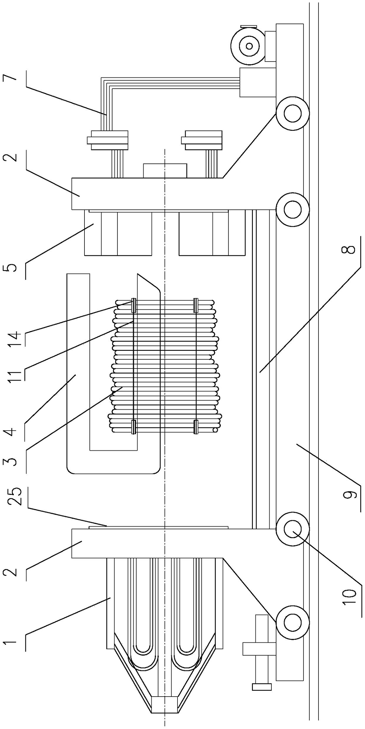
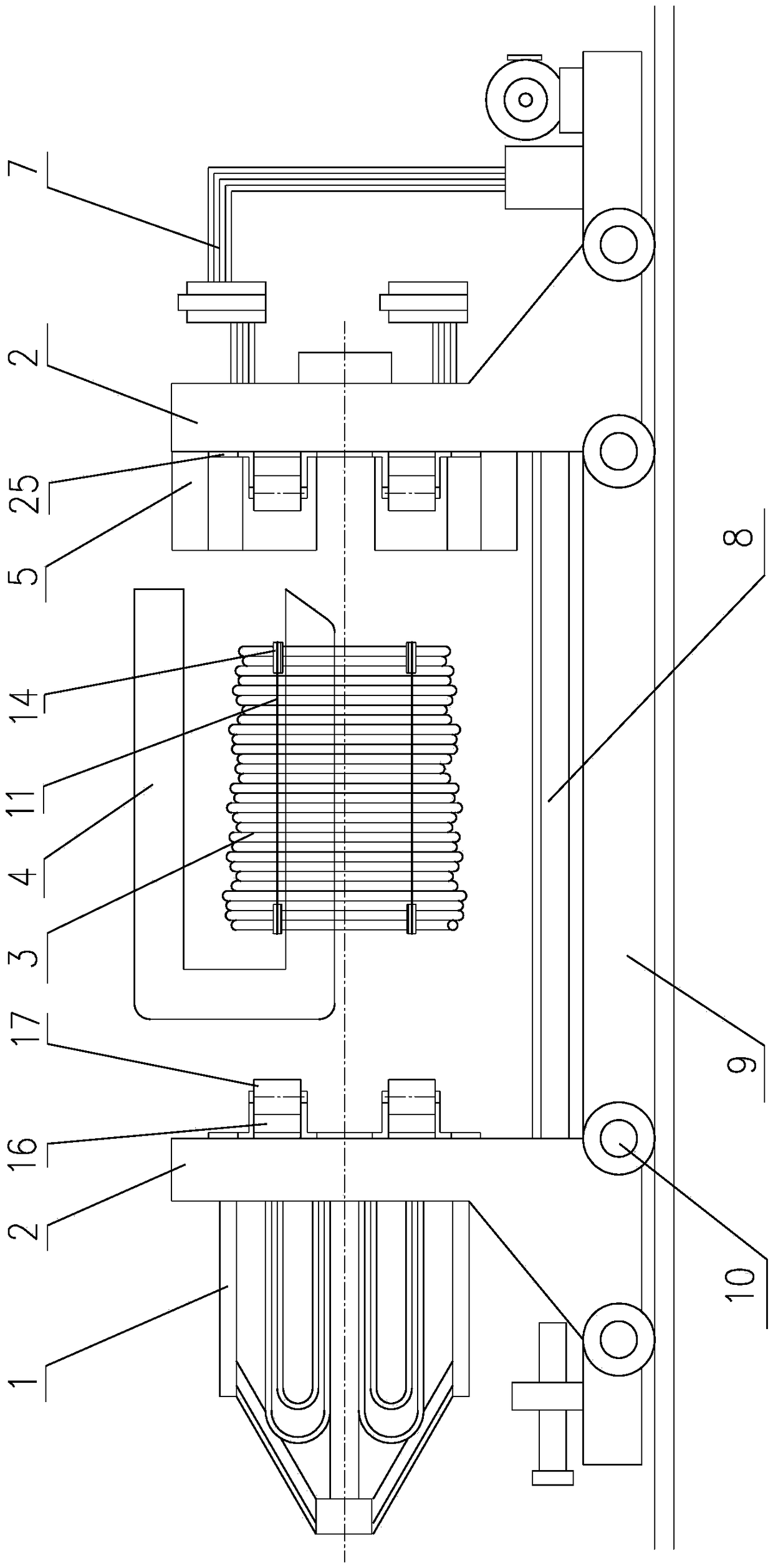
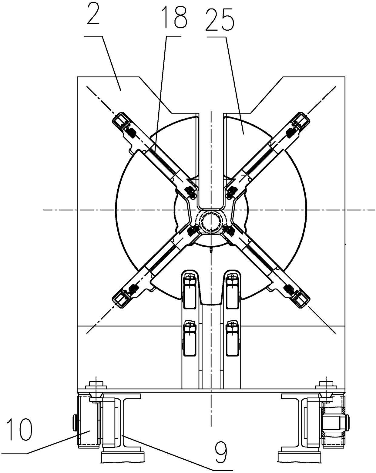
[0071] A gasket placement mechanism for a high-wire wire rod baler, the baler includes two pressing plates 2 that move back and forth at both ends of the pressing direction;

[0072] The two opposing pressing surfaces of the pressing plate 2 are fixed with circular anti-frustration discs 25 with a certain thickness, and the four opposite corners of the pressing plate 2 and the anti-frustration discs 25 are provided with four wire grooves 18 for binding steel wires. The wire groove 18 divides the anti-frustration disc 25 into four fan-shaped plates of upper, lower, left and right;

[0073] At the four opposite corners of the pressing plate 2, conveying rollers 16 and gasket rolls 17 are arranged,

[0074] The gasket roll 17 is connected side by side by a large number of gaskets 14 in a long strip shape, and the winding direction of the single gasket 14 is located on ...


PUM


Abstract

The invention relates to an improved mechanism for machining steel bars into machines and tools in the wire rod packing procedure in the field of steel and iron, in particular to a gasket placement mechanism in the procedure of a high speed wire rod packer, and a relevant gasket structure. According to the gasket placement mechanism of the high speed wire rod packer, gaskets (14) unfolded in the horizontal direction by gasket rolls (17) driven by rotation of conveying rollers (16) driven by a numerical control motor penetrate through channels which are let out by an anti-filing disc (25) to the positions of wire channels (18) of pressing boards (2), pressing strips (19) are arranged above the gaskets (14) and on groove openings of the wire channels (18), the gaskets (14) are parallelograms, the adjacent gaskets (14) are connected with the bevel edges and provided with sawtooth holes (14c) or line concave indentations, the gaskets (14) are metal sheets, and conveying toothed holes (14a)are formed in the corresponding unfolding positions of the gasket rolls (17). The mechanical and automatic gasket placement is achieved, the gaskets (14) are consumables and convenient to manufacturein a specialized mode, special line goods supply is achieved, and the working efficiency and economic benefits are greatly improved.

Description

technical field [0001] The invention relates to an improved mechanism for machines and tools in the process of processing steel bars to form wire rod packing in the iron and steel field, in particular to a gasket placement mechanism and a related gasket structure in the process of a high-wire wire rod packing machine. Background technique [0002] Wire rods produced by steel mills are also called wire rods because they are delivered in wire rods. Before the high wire rod bundling in steel mills in this field does not use the packaging protection gasket, the high wire wire rod is all directly bundled with a baler after being produced and formed, and the bundled steel wire (band) directly tightens the wire rod. Because the binding steel wire of the baler is subjected to a large tensile force, it is easy to be strangled at the contact with the two sides of the wire rod. At the same time, during the transportation process, the two sides of the wire rod are easily damaged by impa...

Claims


Application Information

Patent Timeline
Patent Type & Authority Applications(China)
IPC IPC(8): B65B61/20B65B13/18
CPCB65B13/18B65B27/06B65B61/20
Inventor 张雪松
Owner SHANGHAI WINLONG ENERGY CONSERVATION & ENVIRONMENTAL PROTECTION TECH CO LTD
Why Eureka
Try Eureka