Secure equipment transfer system

a technology of equipment transfer and safety system, which is applied in the direction of religious equipment, lighting support devices, candle holders, etc., can solve the problems of inability to provide a safety system to lock the support structure to either the mobile or stationary platform, and the technique typically proves hazardous, so as to prevent accidental disengagement of the transfer, reduce the cost of manufacturing, and reduce the difficulty of transportation

Active Publication Date: 2013-11-12
NEXXSPAN HEALTHCARE
View PDF20 Cites 14 Cited by
  • Summary
  • Abstract
  • Description
  • Claims
  • Application Information

AI Technical Summary

Benefits of technology

[0017]In accordance with another aspect of the preferred embodiment of the present invention, there is provided a security mechanism that secures a first docking cone, upon engagement to the transfer device, to a first docking cup. The security mechanism only releases the first docking cone from the first docking cup upon insertion and full engagement of a second docking cone in the second docking cup. The security mechanism of this invention prevents accidental disengagement of the transfer device from either the stationary or mobile platforms to which it is docked as it securely locks an engaged docking cone to its respective docking cup. The transfer device may only be disengaged from a first docking cone when another docking cone is fully inserted and engaged in the other docking cup, or vice-versa. The security mechanism operates autonomously without human intervention. It is activated by user control of the vertical movement of the docking activation mechanism, such as the height adjustment of a hospital bed.
[0018]It is therefore an object of the present invention to provide a system for transferring patient support equipment from stationary to mobile platforms that is of low mechanical complexity, and that utilizes fewer, standardized, simpler components to permit low-cost manufacturing and reduced service and warranty costs by minimizing field maintenance and extending the mean time between failures. It is a further object of the present invention to provide a patient transfer and transport system that assures the life support equipment is securely locked to either the stationary or mobile platform so that it cannot be accidentally removed or dislodged, yet allows seamless transfer of the life support equipment between stationary and mobile platforms that automatically engages the security lock during transfer by utilizing a vertical lift mechanism such as a typical, motorized patient bed. It is still a further object of the present invention to provide a patient transfer and transport system that minimizes in-service training of caregivers, by making transfer from stationary to mobile platforms intuitive, minimizing training of transport staff by eliminating or automating critical steps in the procedure, and relying less on memory or alertness of personnel. It is yet a further object of the present invention to provide a patient transfer and transport system that minimizes crevices, exposed fasteners and upward-facing cavities to facilitate effective cleaning and infection control. It is a further object of the present invention to provide a patient transfer and transport system that is relatively insensitive to the misalignment of equipment typically encountered in hospitals during transfers between stationary and mobile platforms. It is still a further object of the present invention to provide a patient transfer and transport system that permits nursing staff to position and re-position the support equipment relative to the patient that allows ready access to the patient and facilitates easy monitoring and control of life-support equipment during transport, minimizes the total footprint of the bed and associated equipment, and minimizes the risk of dislodging fluid lines, cables and leads between equipment and patient during transfer between stationary and mobile platforms. Finally, it is an object of the present invention to provide a patient transfer and transport system that is articulated to allow caregivers full freedom in repositioning the patient support equipment around the patient's head and allows the articulations to be locked in place during transport.

Problems solved by technology

The difficulty arises when, at times, these patients must be transported from their rooms for administering of various hospital services such as surgery, imaging, radiology or special procedures.
These techniques typically prove hazardous because the IV stands may fall and tear out patient connections.
Such patient transports are also inefficient and costly because much staff time is required to prepare a patient for transport and many caregivers are needed for moving the equipment in tandem with the bed along corridors, into elevators and through doors.
U.S. Pat. No. 4,945,592 (Sims) teaches use of the hospital bed as a lifting mechanism but fails to provide a safety system to lock the support structure to either the mobile or stationary platform.
Further the support equipment cannot be placed on the bed in an optimal position for patient care during transport.
Also, conditions on the ground are such that it is difficult to align mobile and stationary platforms for seamless transfers.
A further problem in this system is that the system components are not standardized and are therefore costly, and components generally do not conform to effective infection control requirements.
Similarly, U.S. Pat. No. 7,065,812 (Newkirk) also fails to provide a safety system to prevent accidental dislodging of the equipment support structure from engagement to stationary or mobile platforms.
Arms and docking mechanisms are not standardized and therefore are costly to manufacture, and the support equipment cannot be moved into an optimal location for effective patient care during transport, nor do components generally conform to effective infection control requirements.
US Published Application No. 2006 / 0242763 (Graham) fails to provide a safety system to prevent accidental dislodging of the equipment support structure from engagement to stationary or mobile platforms.
Additionally, the docking elements are arranged vertically above each other in co-axial relationship, which restricts optimal positioning during transport, fails to provide effective articulation between equipment support structure and patient bed, and therefore does not allow optimal in-transport equipment positioning.
The approach is complex and costly as there is no standardization of crucial docking components, and the safety system relies on a complex and costly sliding mechanism.
U.S. Pat. No. 7,661,641 (Wong) teaches a safety system to prevent accidental dislodging of the equipment support structure from engagement to stationary or mobile platforms but also arranges the docking elements vertically above each other in co-axial relationship which restricts optimal positioning during transport, fails to provide effective articulation between equipment support structure and patient bed and therefore does not allow optimal in-transport equipment positioning.
The safety system and the requirement for a mobile base make this approach complex and costly to implement.
These approaches are overly sensitive to misalignment in height and axial orientation of the components to be docked.

Method used


Image

  • Secure equipment transfer system
  • Secure equipment transfer system
  • Secure equipment transfer system

Examples


Embodiment Construction

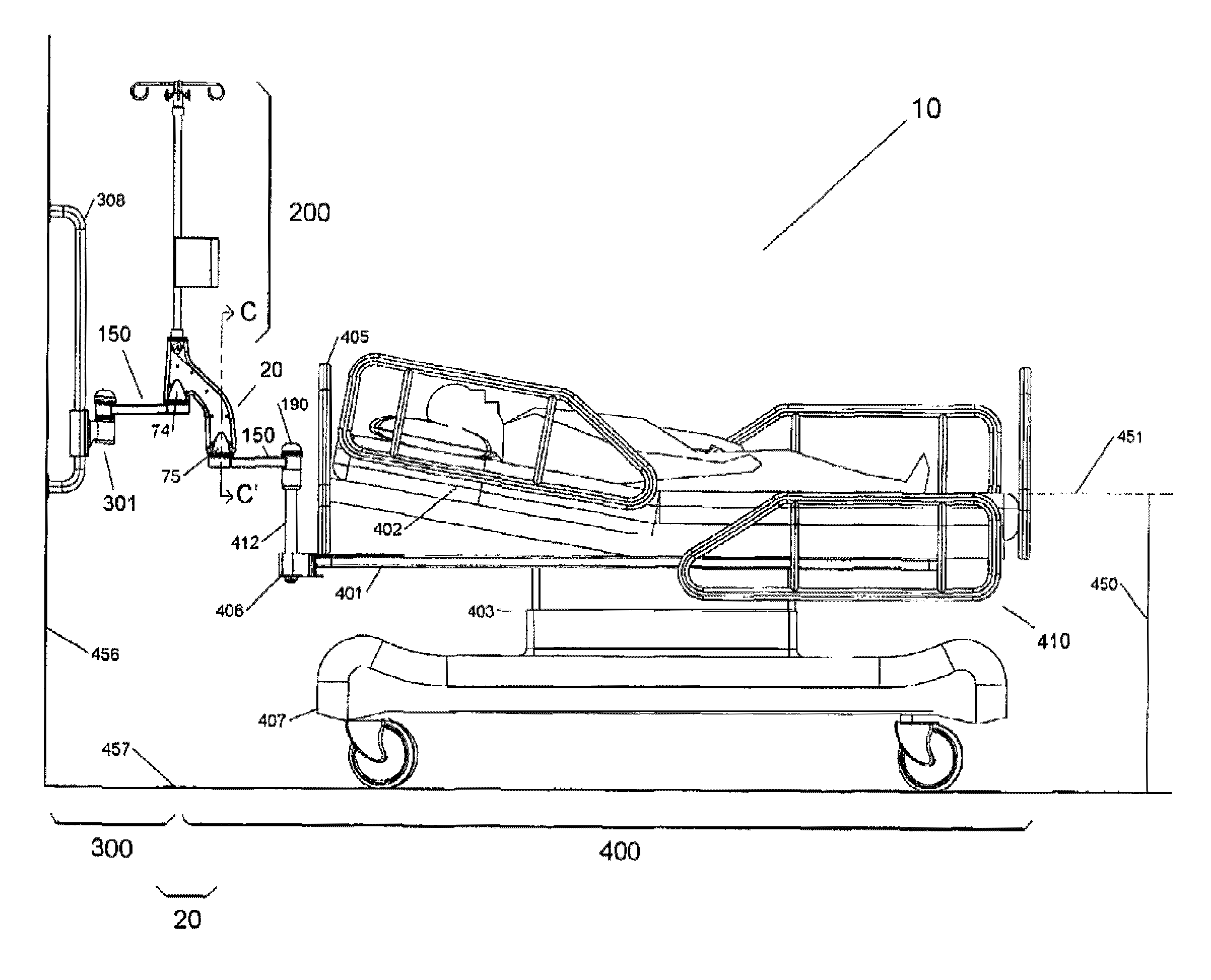
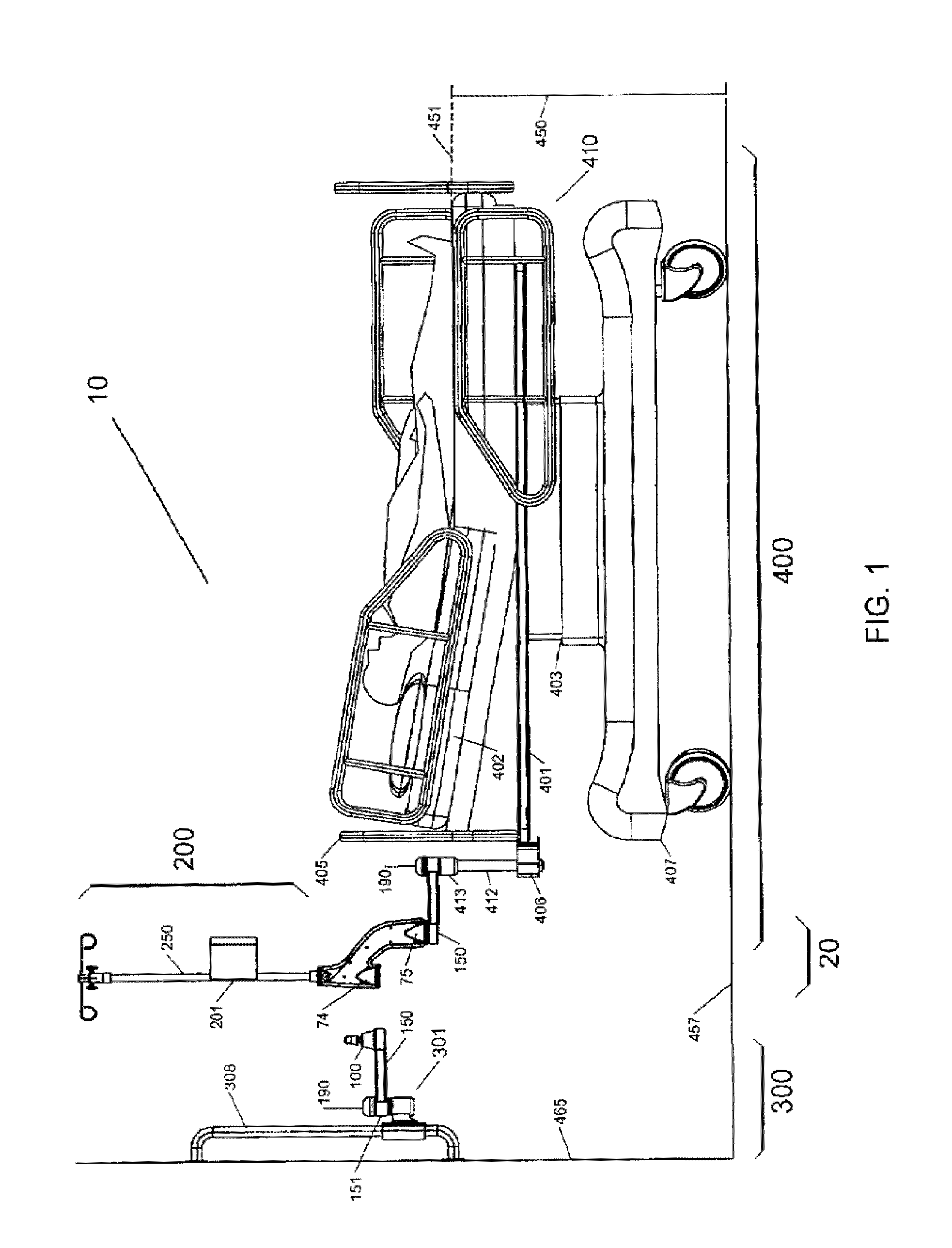
[0048]Now referring to the drawings, the equipment transfer system is shown and generally illustrated in the figures. As can be seen the principal component of the transfer system is a transfer device 20 that can be selectively supported and moved between a stationary support platform 300 and a mobile support platform 400 to facilitate the transfer of patient care apparatus 200 supported thereon.

[0049]Turning to FIG. 1, the transfer system 10 includes a stationary support platform 300, a mobile support platform 400 and a transfer device 20 that supports a patient care apparatus 200 and is capable of transferring the patient care apparatus 200 between a stationary support platform 300 and a mobile support platform 400 and vice-a-versa. Within the scope of the present invention the term “transfer” refers to transferring patient support equipment between stationary support platforms including walls, headwalls, ceiling-mounted or wall-mounted booms from various manufacturers, free-stand...


PUM


Abstract

An equipment transfer device is provided that is transferable from one support to another support. The transport device is formed as a housing that has two spaced apart, generally parallel recesses, which form docking cups that are open to the bottom. Each docking cup is configured to receive a docking cone that is supported on a structure and is capable of moving in generally a vertical direction into engagement or out of engagement with their respective docking cups. A support post is also supported by the housing and protrudes from the upper end thereof as a base to which an equipment support structure is attached. In this manner the transfer device can be transferred from one docking cone to another with minimal handling and virtually no possibility of dislodgement.

Description

CROSS-REFERENCE TO RELATED APPLICATIONS[0001]This application is related to and claims priority from earlier filed U.S. Provisional Patent Application No. 61 / 332,918, filed May 10, 2010.BACKGROUND OF THE INVENTION[0002]The present invention relates generally to medical equipment transfer systems. More specifically, the present invention relates to a transfer system for reliably, safely and securely transferring life support apparatus between various support platforms when transporting critically ill patients.[0003]In the daily care of critically ill patients, a great diversity of medical equipment, including infusion management equipment and supplies, pressure transducers, physiological monitors and other equipment is employed. Such equipment typically is set up at the patient's bedside where it is supported by various stands, racks or hangers. For example, the equipment may be supported by 5-star floor stands, attached to headwalls, suspended from booms that are affixed to the ceil...

Claims


Application Information

Patent Timeline
Patent Type & Authority Patents(United States)
IPC IPC(8): E04G3/00F16M13/00A47B71/00
CPCA61G7/1025A61G7/1073A61G12/005A61G7/0015A61G2203/80
Inventor BALLY, ALEXANDER
Owner NEXXSPAN HEALTHCARE
Why Eureka
Try Eureka